Yasmin Arbab, Connie Brasil, Lynne Martin, Gregory Costedoat, Stefan Blandin, Charles Walter, Deborah Bakowski (2025). Development of a Graphical User Interface for the Advanced Capabilities for Emergency Response Operation’s Portable Airspace Management Concept. In: Human Factors in Design, Engineering, and Computing. AHFE Open Access, vol. 199, pp. 481–492. https://doi.org/10.54941/ahfe1006860
Uncrewed Aircraft Systems (UAS) have emerged as a critical tool in modern wildland firefighting operations, providing real-time data collection, mapping, and communication capabilities in areas that may be difficult or dangerous for crewed aircraft to access. Effective integration of UAS into these high-stakes environments requires structured airspace management systems capable of supporting real-time coordination and situational awareness. Building on the foundational concepts of NASA Ames Research Center’s UAS Traffic Management (UTM) system, the following describes the development of a graphical user interface for the Advanced Capabilities for Emergency Response Operations (ACERO) project, focusing on Second Shift Capabilities (SSC), designed for low-visibility conditions. The user interface (UI) integrates data from multiple sources to support airspace management, coordination, and deconfliction. Drawing upon lessons learned from NASA’s Scalable Traffic Management for Emergency Response Operations (STEReO) research activity, the ACERO team developed a robust, field-ready research prototype informed by a structured systems engineering process. Here, we trace the buildup of the UI from high-level systems engineering requirements to its field-ready prototype which was evaluated during a Spring 2025 field demonstration.
The increasing versatility and capability of Uncrewed Aircraft Systems (UASs) has led to their integration into a variety of operational domains. One prominent example is their use in disaster and emergency response, where UAS are being deployed to support wildland fire management efforts (Martin et al., 2023).
UASs offer several key advantages when being deployed during emergency operations. For example, UAS can generally operate in conditions or at
altitudes deemed too hazardous for crewed aircraft. As such, they are well suited for missions like real-time fire mapping, perimeter monitoring, and prescribed burns, particularly during nighttime or low-visibility conditions (Martin, Arbab, & Mercer, 2021). However, safely managing air traffic over an incident requires high levels of communication, coordination, situational awareness, and extensive training—functions that, at present, are achieved by a human “aerial supervisor” tracking and deconflicting incident aircraft via radio while in the air themselves (Martin et al., 2022).
While UASs offer valuable capabilities for supporting wildfire response, their integration into shared airspace is hindered by a key safety challenge— their lack of visibility (Martin et al., 2022). To address this challenge, it is critical to develop tools that enhance situational awareness for both UAS operators as well as neighboring aviators. Tools that provide a clear, shared understanding of airspace activity can reduce uncertainty and improve decision-making for UAS operators. As uncrewed aircraft continue to play a larger role in emergency responses, systems that enhance situational awareness will be vital for ensuring that safety is not compromised in the pursuit of operational efficiency.
BACKGROUND
Uncrewed Aircraft Systems Traffic Management The UAS Traffic Management (UTM) system, developed at NASA Ames Research Center, laid the groundwork for coordinating UAS operations through digital flight intent sharing. In the UTM framework, operators submit their planned flight area, in the form of four-dimensional (4D) volumes of airspace, allowing the system to deconflict operations in time and space (FAA, 2020). By aggregating aircraft telemetry, operational volumes, airspace restrictions, and potential conflicts, UTM enables the management of UAS operations. The UTM Service Supplier (USS) facilitates this process by ensuring that operations are deconflicted, providing feedback, and monitoring conformance to the approved operation intent.
While UTM has demonstrated considerable promise for managing UAS operations at scale, its reliance on persistent network connectivity presents challenges in the context of emergency response. Wildland fire incidents often occur in remote, rugged terrain where the communication infrastructure is generally limited, and external conditions change rapidly. To address these unique operational demands, NASA explored additional approaches to supporting local airspace awareness and tactical decision making in wildland fire operations—leading to new prototype tools tailored to the wildland firefighting environment.
Scalable Traffic Management for Emergency Response Operations Building on several of the foundational concepts introduced by the UTM system, NASA’s Scalable Traffic Management for Emergency Response Operations (STEReO) research activity explored how elements of the UTM paradigm could be adapted to meet the unique challenges of using
Development of a Graphical User Interface for the Advanced Capabilities 483
UAS in wildland fire response (Martin, Arbab, & Mercer, 2021). In collaboration with subject matter experts (SMEs) from the U.S. Forest Service (USFS) and CAL FIRE, the STEReO team investigated tools that support localized airspace awareness and decision making in communications-limited environments (Martin et al., 2023).
One of the key outcomes of this work was the development of the UAS Pilot-kit (UASP-kit), a lightweight, field-deployable system designed to enhance situational awareness in areas without Wi-Fi or cellular connectivity. Although the UASP-kit does not facilitate the exchange of operational data between users, it reflects some core UTM concepts, particularly, the planning of volume-based UAS operations (Martin et al., 2023).
NASA’s ACERO The Advanced Capabilities for Emergency Response Operations (ACERO) project, led by NASA Ames Research Center, seeks to enhance the safety, effectiveness, and efficiency of emergency response operations, with a particular focus on wildland firefighting. ACERO’s Second Shift Capabilities (SSC) subproject explores how UAS can extend aerial support in low-visibility conditions while addressing some of the challenges that UAS operators face in the wildland firefighting environment (Yoo et al., 2024). These challenges include building situational awareness in dynamic airspaces and sharing real- time telemetry while operating in locations with degraded communications.
To support these goals, the ACERO team has developed the Portable Airspace Management System (PAMS), a research prototype tool designed to promote shared airspace awareness and support more efficient airspace management in degraded-communications conditions.
The Portable Airspace Management Concept PAMS builds on prior research and prototype technologies, including the UASP-kit. The UASP-kit was designed for a single uncrewed vehicle, not a fleet of UASs. PAMS introduces multi-user coordination and integrates multiple data sources.
Central to this evolution was the creation of the Wildland Fire Service Supplier (WFSS). Modeled after UTM’s USS architecture, the WFSS provides services such as planning, strategic conflict detection, conformance monitoring, and constraint management for UASs operating in the wildfire environment. The WFSS compares all UAS operations submitted to the system to prevent spatial and temporal conflicts between UAS operations and monitors aircraft conformance to their submitted volume(s) for the duration of the operation. The WFSS also checks that submitted UAS operations do not violate Temporary Flight Restrictions (TFRs) and ensures that UAS operations stay within authorized boundaries.
The WFSS assigns operational “states” to indicate the status of an operation, including Submitted, Validated, Active, Non-Conforming, and Closed. For example, if the Submitted operation meets all specified operator Application Programming Interface (API) requirements, does not have any volume overlaps with other operators, and is within the TFR, the operation is
Validated. If a conflict is detected, the WFSS prompts the user with a “replan required”message. Upon takeoff, the operation transitions to the Active state. If the aircraft deviates from its operation volume, it is Non-Conforming. The Closed state indicates that the UAS has landed. There is also an Approved stage that occurs after Validated but before Activated. Approved is not a formal WFSS state, it is a verbal communication stage incorporated into the PAMS workflow to simulate the process of an aerial supervisor coordinating air traffic at a wildland fire incident.
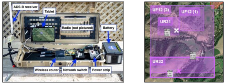
Each PAMS unit, referred to as a PAMS case (Figure 1, left), is equipped with a tablet that houses the system software and serves as the platform where the user interface (UI) displays operational information. The PAMS case also contains a handheld radio (not pictured) to support digital information exchange, an Automatic Dependent Surveillance-Broadcast (ADS-B) receiver to track nearby crewed aircraft, and other hardware components supporting the shared data capability. The PAMS cases allow users to interface directly with the WFSS, enabling real-time data sharing and coordinated UAS operations. For a full description of the PAMS case components, see Bakowski et al. (2025).
Figure 1: PAMS case (left) and PAMS UI with three active operations and their corresponding vehicle telemetry represented by UAS icons and data tags (right).
Portable Airspace Management System Engineering Requirements ACERO adopted a structured systems engineering process to ensure that PAMS development efforts aligned with the goals of the project. To do this, the systems engineering team conducted numerous interviews with the technical team to identify development priorities and translate them into formal “shall” statements, which are clear, testable descriptions of what the system must do.
These requirements were organized into tiers to help track dependencies, align development with high-level objectives, and manage risk. The Airspace Management key requirement stated the system “shall share UAS operations information to facilitate coordination between operators within an emergency response area.” This requirement captures the intent behind the overall PAMS capability while also setting a clear benchmark, if shared
Development of a Graphical User Interface for the Advanced Capabilities 485
information does not support coordination, the requirement is not met. The following sections highlight the UI team’s implementation of these system requirements.
With the PAMS requirements formally established through the systems engineering process, the UI Team translated these abstract system-level needs into tangible interface features/workflows (see high-level UI requirements in Table 1).
Table 1: Level 1 and Level 2 UI requirements.
Table available in the original PDF paper.
Req. ID Short Title Requirement Text UI.1 User Interface System shall provision user accessibility and awareness through a field-deployable interactive display UI.1.1 WFSS Interface UI shall provide an interface to WFSS UI.1.2 Data Processing Tool Interface
UI shall provide an interface to the data processing tool (Fire data and ADS-B data display) UI.1.3 UI System Data Logging UI system shall record user interface data as specified in the Data Management Plan
Each “shall”statement served as a design driver, helping to define the scope of individual UI components which guided decisions about the interface’s layout, data presentation, and user interaction patterns.
The software component requirements listed in Table 1 each included numerous sublevel requirements and spanned multiple functionalities. For example, within the WFSS interface (UI.1.1), the UI was required to support the full lifecycle of UAS operations. This included the ability to create, modify, send, receive, and display 4D UAS operation volumes, receive and display UAS operation state changes and conformance monitoring status, and depict whether an operation was Validated, Approved, Active, or Closed. The UI was also required to receive and depict airspace constraints, strategic conflict information, and real-time UAS telemetry data from the WFSS. As the interface for the Data Processing Tool (DPT), a decision support software, the UI was required to ingest and display ADS-B data and fireline data (UI.1.2). All user actions and system messages were logged by the interface in accordance with the Data Management Plan (UI.1.3).
PORTABLE AIRSPACE MANAGEMENT SYSTEM USER INTERFACE The PAMS interface consolidates key airspace, operation, and system data into a single viewpoint with interactive features tailored to meet functional requirements. In addition, all software interacting with the UI must follow the established operator API, which is the programming interface that enables external applications to interact with the UI and the UI to retrieve required information.
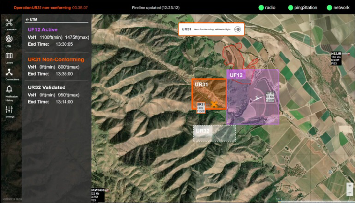
The PAMS interface is composed of three main components: 1) a status bar, 2) an interactive map, and 3) a sidebar menu (see Figure 2). Together, these components meet the high-level requirements and provide users with access
to real-time airspace information, and tools for managing UAS operations and customizing their map view.
The UI evolved over the course of development through an iterative process that involved collaboration between researchers and developers. This process ensured that the UI met necessary functional requirements while providing a user experience that intuitively and meaningfully increases situational awareness.
Status Bar The status bar spans the top of the UI and shows three categories of information: 1) operation status, 2) new TFR and fireline updates, and 3) system status. 1) Operation status. The left side of the status bar displays at- a-glance information about the user’s own operation status (e.g., Validated, Replan Required, Active). Once an operation has been activated, its current state (i.e., Active or Non-Conforming) is displayed with the time remaining until the operation expires. 2) TFR/Fireline status. The center of the status bar displays timestamped updates when new TFRs or firelines are shared (see Figure 2). 3) System status. The right side of the status bar shows three real-time system status indicators: 1) radio signal, 2) ADS-B receiver, and 3) network connection to the WFSS system.
Figure 2: PAMS UI: view of three different operations/states from the perspective of UR31. As reflected in the UTM Panel on the left, UR31 is non-conforming (see non- conforming alert banner, orange volume on map, orange operation state text in status bar), UF12 is active (see purple volume), and UR32 is in the Validated state (see white, dashed outline), prior to receiving approval.
Development of a Graphical User Interface for the Advanced Capabilities 487
Interactive Map The map is the central visual component of the UI and presents multiple categories of information, including: 1) UAS operation volumes, 2) UAS telemetry, 3) airspace constraints, 4) ADS-B data, and 5) fireline data. The UI displays a satellite map style by default while also supporting multiple other map styles that the user can select (e.g., topographic, street). 1) UAS operation volumes. The UI depicts the user’s operation volume(s), along with the volumes of other operations connected to the WFSS, as rectangular shapes on the map. To enhance saliency, the user’s own operation volumes are shown with a bolder border. Each operation volume includes the callsign (and the volume number if there are two) to indicate ownership. The current state of each operation is represented using both color codes and patterns on the volume shapes (i.e., Submitted (dashed black), Validated (dashed white), Approved (solid white), Active/conforming (purple), Non- Conforming (orange), and Closed (solid black)). 2) UAS telemetry. UAS telemetry appears on the map as UAS icons accompanied by data tags. The UAS icon reflects the UAS type based on the callsign prefix, with callsigns starting with “UF” mapping to a fixed-wing icon and those starting with “UR” mapping to a multi-rotor icon. Each data tag shows the callsign, speed (in knots), and altitude (in feet MSL). The user’s own UAS icon appears purple when the operation is Active/conforming and orange when it is Non- Conforming. All other UAS telemetry icons appear white for visual clarity. 3) Airspace constraints. Currently the UI receives and displays TFRs as a type of airspace constraint. A TFR is depicted as a light blue dashed polygon on the map. Only one TFR can be displayed at a time, and once received, it cannot be removed from the WFSS. While the TFR can be toggled on/off visually from the UI, it is recommended that it be displayed because TFRs are a prerequisite for operation submission, as they are typically established around a wildland fire to separate incident air traffic from general aviation and must fully encompass UAS launch sites and flight areas. 4) ADS-B data. ADS-B data, or ADS-B tracks, as provided by the DPT, are shown on the map as aircraft icons representing different aircraft types/categories, each accompanied by a data tag with real-time flight state data. Each data tag includes the aircraft’s callsign, speed (in knots), pressure altitude (in feet MSL), and source ID (i.e., which PAMS case the data originated from). DPT fuses and shares ADS-B data collected from multiple PAMS cases. 5) Fireline data. Fireline data provided by DPT is visualized as a polygon with a solid red border and light red fill (see Figure 2). Similar to TFRs, only one fireline can be displayed at a time, and it should not be removed once received (the fireline overlay can be toggled on/off by the user). The fireline is updated when new fireline data are received.
Sidebar Menu The sidebar menu is displayed on the left side of the UI and allows users to access several key panels: 1) Operation, 2) UTM, 3) Layers, 4) Connections, 5) Notification History, and 6) Settings. 1) Operation panel. The Operation panel allows users to create and manage operation information through text
input fields. Users can add a new volume to the map and use either the text entry fields to specify the height and width of the volume (nautical miles) or the handles positioned at each corner of the volume to resize the volume’s shape. Currently, only rectangular-shaped volumes are supported, and each operation submission is limited to two volumes. To create an operation, users specify the vehicle’s callsign, the minimum and maximum altitude for each volume, the start time, and duration. 2) UTM panel. The UTM panel enables the user to view read-only information about participating WFSS operations (see Figure 2). This includes the callsign, minimum and maximum altitudes, and the current operation state. 3) Layers panel. The Layers panel allows users to manage map layers including, the base map (e.g., satellite, topographic) and the visibility of the TFR and fireline. 4) Connections panel. The Connections panel is currently a placeholder and is intended to display detailed information about system connectivity. 5) Notification History panel. The Notification History panel allows users to view a descending history of updates related to operations, TFRs, and firelines. Each event is timestamped and can be expanded to view details. 6) Settings panel. The Settings panel enables the user to manage ADS-B settings. If ADS-B filters are toggled on, the user can filter ADS-B data by altitude and/or distance using sliders and/or text fields.
User Interface Development and Evolution The PAMS interface was developed through ongoing collaboration between researchers and developers, with researchers testing new software builds in both laboratory settings using simulated data and outdoor environments using live data. These tests focused on identifying bugs and assessing how well the UI supported the functional requirements. The lower-level UI requirements specified how information, such as operation volumes, UAS telemetry, and TFR violations, should be visualized on the UI. Many of the UI enhancements were implemented in response to specific feedback tied to lower-level UI requirements.
For instance, while the UI correctly rendered all operation volumes on the map, users reported difficulty quickly distinguishing their own operation. This led to visual enhancements, such as applying a thicker border to the user’s operation volume and designing a more prominent data tag to improve saliency. These changes directly addressed the lower-level requirement that the “UI shall enhance the saliency of ownship operation,” including the more specific guideline that the “UI shall use a bolder volume shape border for ownship compared to other operations.” Similarly, the UI initially color- coded all UAS icons to reflect the operation state, but users found it difficult to distinguish their own UAS from others. In response, the design was revised so that only the user’s own UAS icon is color-coded based on operation state, while all other UAS icons remain white. This change improved the user’s ability to quickly track their own UAS. Figure 1 (right) depicts three operations and their corresponding Active volumes with telemetry represented by the vehicle icon and data tag. UR32 represents the user’s “own” UAS. Its volume shape and data tag feature thicker borders for
Development of a Graphical User Interface for the Advanced Capabilities 489
saliency, the callsign is displayed in the upper left corner of the volume to clearly indicate ownership, and the vehicle icon is filled in to match the current operation state.
Another instance of previous user confusion was related to TFR conflicts. Initially, when an operation volume breached the TFR boundary, the UI displayed a generic “replan required”message but had no way of determining the cause of the conflict, making it difficult to resolve the issue. To address this, a fix was made to specify in the status bar whether the conflict was lateral or vertical.
After multiple iterations and extensive testing, the UI incorporated numerous enhancements aimed at addressing user feedback and aligning the interface with the functional requirements. This development process ensured that the UI was prepared for field testing, where it would be used for flight demonstrations.
FLIGHT DEMONSTRATION To evaluate the field readiness of the UI for PAMS, the ACERO team carried out a series of live-flight test scenarios over a two-week period near the Salinas foothills in California during Spring 2025 as part of the first development milestone. Each test run involved three flight crews simultaneously flying a UAS from their respective remote launch sites; two smaller multi-rotor (Type 3) and one larger, fixed-wing (Type 1) equipped with a relay radio payload. In addition to the flight crew, there were also two members of the ACERO team stationed at each launch site, a PAMS Operator and a human factors researcher.
During each run, either a flight crew member or a firefighting SME used the PAMS interface, with support from the PAMS Operator, to complete a series of tasks intended to validate key UI requirements and provide subjective input and feedback. Users monitored the UI to maintain situational awareness of the surrounding airspace throughout the run.
A total of four PAMS cases were utilized during each run; one by each of the three flight crews and a fourth by a UAS aerial firefighter SME assigned to be the “Approver.” The Approver role was intended to emulate an aerial supervisor, who is responsible for coordinating the airspace above a wildland fire. During testing, the “Approver” gave verbal approval to each of the three UAS flight crews.
Flight Test Scenarios and Execution Prior to each run, the team ensured that the PAMS cases were not able to establish ground connectivity – making information exchange between the cases dependent on connectivity to the airborne radio carried by the Type 1 UAS, as designed.
At the beginning of each run, the team stationed with the Type 1 UAS flight crew submitted two operation volumes to the WFSS and received approval to take off. Before beginning their operations, both Type 3 multi-rotor UAS teams waited for their PAMS cases to establish connectivity with the airborne
radio on the Type 1 UAS, before submitting their operation volumes to the WFSS.
To ensure safe operations, the PAMS Director, who was responsible for the PAMS case research readiness, coordinated with the Flight Ops Flight Test Director who was responsible for the coordination between Flight Ops and PAMS research operations.
The test procedures were designed to evaluate PAMS performance in a real-world setting across a range of scenarios that included one nominal scenario and four off-nominal scenarios (TFR violation, overlapping volume, non-conformance, no radio connection). During nominal test runs, users submitted an operation that was located within the boundary of the TFR and deconflicted from other volumes, and remained in conformance with their own volume(s) for the entirety of their flight. For the TFR violation runs, users were instructed to submit an operation volume that deliberately violated the boundaries of the TFR. For the operation volume conflict runs, users submitted a volume that overlapped with one of the existing volumes on the map. For the non-conformance runs, users were instructed to submit an operation volume that their UAS would intentionally fly outside of (to ensure safety, users carefully coordinated with Flight Ops). Finally, the no radio connection runs were used to demonstrate how the system behaved prior to establishing connectivity with the relay radio. Once the airborne relay was active, users observed how the system shared information. These structured test scenarios ensured that the system was exercised under a variety of conditions to verify the overall system requirements and to validate some of the complexities that UAS crews face during wildland fire operations.
User Interface Validation Through Testing The five test scenarios allowed the UI team to verify that the PAMS interface met functional requirements under a range of conditions. In all scenarios, the PAMS interface successfully received and displayed UAS operations, states, volumes, telemetry, and TFRs from the WFSS, as well as ADS-B and fireline data from DPT. These data were rendered on the map and in the panels in near real-time. The four off-nominal scenarios also tested how the PAMS interface handled more complex system behaviors. For example, the conformance- monitoring requirement was tested when a UAS deviated from its operation volume (see operation UR31 in Figure 2).
Across these scenarios, users were generally able to interpret system responses, manage/revise their operations, and maintain awareness of the airspace. These tests also gave SMEs and crew members the opportunity to experience and evaluate the PAMS interface in near-realistic conditions, leading to valuable feedback that will inform next steps for future design iterations.
CONCLUSION AND NEXT STEPS ACERO’s Spring 2025 field demonstration marked an important step toward enabling digital coordination of UAS operations in wildland fire response operations. A key enabler of this was the PAMS interface, which allowed
Development of a Graphical User Interface for the Advanced Capabilities 491
users to view airspace activity and coordinate UAS operations in real time. Feedback from users during the demonstration provided valuable insights into how the UI can better support UAS operators. As development continues, the UI will remain central to ensuring that users can effectively access, interpret, and act on information in time-sensitive and complex operational environments.
ACERO’s second development phase will focus on expanding and refining current features and improving overall system performance. One of the key goals is to address network latency issues experienced during the field tests, which impacted the timeliness and consistency of data exchange between the PAMS cases (Wu et al., 2025). For the interface, future efforts will focus on developing role-based UI modes to support more tailored workflows, particularly in mission planning and information sharing. The UI will also be updated to support additional functionality, including creating polygon- shaped volumes as well as, improvements to existing features based on user feedback. Furthermore, as new tools and capabilities from other software components are integrated into the system, the UI must evolve to incorporate and display the information (e.g., fire, weather, terrain data) in a way that supports shared situational awareness, enabling users to see and act on relevant information within a single, cohesive interface.
ACKNOWLEDGMENT
The authors thank the SMEs – members of CAL FIRE’s Tactical Air Operations Program and Global UAS Solutions for their invaluable feedback and participation in the flight test demonstration. We extend our appreciation to industry partner, Overwatch Aero, who were critical to the execution of the demonstration. We thank the property owners of the ranch who graciously accommodated our team.
REFERENCES
Bakowski, D. L., Martin, L., Brasil, C. L., Arbab, Y., Costedoat, G., Blandin, S. A., Walter, C. M., & Ghatas, R. (2025). Integration and Testing of a UAS Airspace Management System in the Wildland Firefighting Environment. Applied Human Factors and Ergonomics (AHFE) International Conference Hawaii Edition, Honolulu, HI, December 8–10, 2025. Federal Aviation Administration (FAA). (2020). UTM Concept of Operations,
Version 2.0. FAA, U.S. Department of Transportation, Washington, D. C. https://www.faa.gov/sites/faa.gov/files/2022–08/UTM_ConOps_v2.pdf Martin, L., Arbab, Y., & Mercer, J. (2021). Initial Exploration of STEReO (Scalable Traffic management for Emergency Response Operations) System User Requirements for Safe Integration of Small UAS. 40th IEEE/AIAA DASC, San Diego, CA, Oct 3–7, 2021. https://doi.org/10.1109/DASC52595.2021.9594419 Martin, L., Arbab, Y., Roberts, L., Mercer, J., Walter, C., McCarty, W., &
Sheehe, C. (2022). Developing an Unmanned Aircraft System Pilot Kit (UASP-kit) for Wildland Fire UAS Operators. AIAA AVIATION Forum, 2022–4003, June 27–July 1, 2022, Chicago, IL. http://doi.org/10.2514/6.2022–4003
Martin, L., Roberts, L., Mercer, J., Arbab, Y., Walter, C., McCarty, W., Sheehe III, C., & Fuller, D. (2023). Initial Testing of the Uncrewed Aerial System Pilot Kit (UASP-Kit) in Operational Settings. 22n ISAP, May 31–June 3, 2023. https://corescholar.libraries.wright.edu/isap_2023/48 Wu, M. G., Munishkin, A. A., Jung, J., & Xue, M. (2025). Development of a Portable
Airspace Management System for Wildland Fire Operations. Proceedings of the AIAA AVIATION Forum, AIAA-2025–3167, Las Vegas, NV, July 21–25, 2025. https://doi.org/10.2514/6.2025–3305 Yoo, H-S., Monheim, S., Martin, L., & McSwain, R. (2024). Advancing Wildland Fire Response with NASA’s Second Shift Capabilities. 43rd AIAA DATC/IEEE DASC, AIAA-2024–3286, San Diego, CA, September 29–October 3, 2024. https://doi.org/10.1109/DASC62030.2024.10749113
LISTED IN THE AHFE DIGITAL BOOKSTORE CATALOGUE
Explore the complete digital volume
Human Factors in Design, Engineering, and Computing
Read this individual research paper free through the original publisher, or explore the full digital proceedings book.
ISBN 978-1-964867-75-5
Explore this ISBN in the AHFE Bookstore ↗Listed in the July 2026 bookstore catalogue; search by ISBN to confirm current availability · Digital book purchase optional