Andy Lapping, Kerim Cakmak (2018). The Systems Modeling Language and its Application to Railway Signaling Systems. In: Advances in Human Factors, Software, and Systems Engineering. AHFE Open Access, vol. 4. https://doi.org/10.54941/ahfe100127
The Object Management Group (OMG) Systems Modeling Language (SysML) defines a general-purpose language for the modeling of systems engineering products. It supports activities across the lifecycle such as specification, analysis, design, verification and validation. Whilst widely used in domains such as Aerospace and Defense, the language has been less used in Railway Signaling Systems. However Railway Signaling Systems are complex, safety critical systems and would benefit greatly from the application of SysML, as this paper intends to show.
Railway Signaling Systems are inherently complex with many moving parts and safety interlocks and as such can be difficult to understand, implement and test. More and more of the innovation seen in the rail industry is driven by software, whereas historically these systems have been relay driven or even purely mechanical. With this increase in software comes even more complexity. SysML has many applications in such systems, from real implementation – that is taking a set of Requirements and driving them through specification, implementation and test – through to purely educational purposes. Many of the concepts in Standard Signaling Principles can be somewhat esoteric and difficult to grasp. I recall one conference in particular some years ago when I used a SysML model to explain the principles of Absolute Block Working in ten minutes. After the presentation an engineer approached me and commented that, until that day, he had never understood Absolute Block. Such is the power of graphical modeling – and execution of those models.
The benefits of modeling are many. Models enable us to manage complexity of systems by simplifying and abstracting the essential aspects of a system and thus increase our understanding of it. Models help in communicating ideas – the old adage of a picture painting a thousand words is never truer. Can you imagine describing a wiring diagram without the graphical representations? Model execution allows a system design to be verified and validated, uncovering new Requirements and reducing uncertainty and risk. Traceability is also a key aspect of safety critical designs, and models allow you to document the design decisions and the justifications for those decisions.
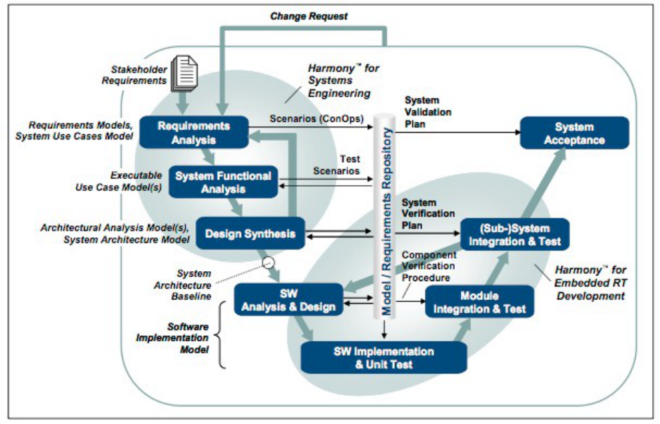
However it should be noted that SysML is merely a language, it is entirely possible to build ‘bad’ models – incorrect, incomplete or just incomprehensible. To ensure the integrity of the model, a robust workflow should be used. Which parts of the language should be used? for what purpose? when should they be employed? Having a consistent and coherent answer to these questions ensures that related models are built in the same way – and that those models are ‘good’ models. This paper presents an example system – modeled following the IBM Rational Best Practices for Model Based Systems Engineering – informally known as Harmony-SE. This process and recommended workflow is described in the version 4.1 of the IBM Rational Harmony Deskbook (ref 1), see figure 1 – which should be referred to as the complete reference during this paper.
Figure 1: Rational Integrated Systems/Embedded Software Development Process Harmony
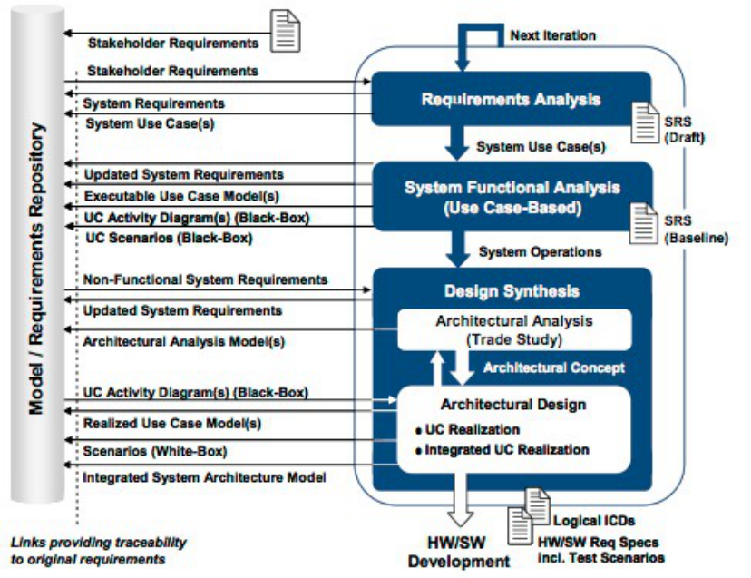
OVERVIEW OF HARMONY-SE WORKFLOW The workflow is broken down into three main phases.
Requirements Analysis In Requirements Analysis, stakeholder requirements are translated into a coherent set of system requirements – divided into functional (what it should do) and quality of service (how well it should do it). It should be noted that this step is often performed outside of the model – usually in a formal requirements management tool such as IBM Rational DOORS. The system requirements are then grouped into Use Cases – which form the starting point of the model.
Functional Analysis Functional Analysis focuses on the identification of system functionality – that is the key functions of the system and the order and conditions in which they occur. This phase is performed iteratively and incrementally, as each Use
Case becomes a Use Case Model that may be executed to verify and validate the requirements with which it was associated during the Requirements Analysis phase. Use Case models allow us to confirm a common understanding of the requirements, but also to identify duplicate requirements, requirements that overlap or conflict as well as missing requirements. Each Use Case Model may be built independently and in parallel – perhaps by separate teams.
Design Synthesis Design Synthesis focuses on developing a set of components (products, systems, hardware/software elements) that can perform the required functions identified in Functional Analysis, whilst also fulfilling the Quality of Service requirements. Design Synthesis is further broken down into Architectural Analysis – during which model-based trade studies allow selection of optimized architectures (ref 2) and Architectural Design, which focuses on the allocation of functions and requirements to the selected architecture.
Figure 2: Harmony-SE Phases
RAILWAY EXAMPLE PROBLEM Now that the overall workflow has been discussed, this technique will now be demonstrated using a real life example, showing how a model based approach using an industry standard modeling language, SysML, leads to a more robust design.
The example explores the concept of an Automatic Train Protection System (ATP). As I’m sure the system described here is familiar to the reader – we will not delve too deeply into the Requirements of such a system but rather explore how those Requirements would be modeled. The basic premise of an ATP system is that it can identify potentially unsafe conditions and warn or even take over from the driver, slowing or stopping the train before those conditions become dangerous. A simple premise – but in reality a very complex system.
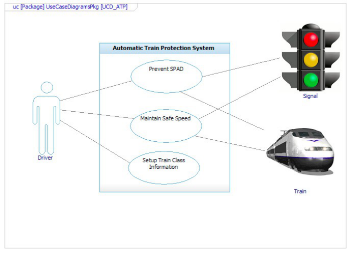
Requirements Analysis As previously stated the stakeholder requirements will not be explored in this paper, or their translation into a set of system requirements. Suffice it to say that the starting point is a set of textual system requirements, stored (in this case) in IBM Rational DOORS. Those Requirements may be represented in the modeling tool – in this case IBM Rational Rhapsody, so that they may be grouped into Use Cases. Note that the Requirements are brought into Rhapsody through an open standard that allows tool interoperability, Open Standards for Lifecycle Collaboration (OSLC) (ref 3) – allowing the modeler to link the existing Requirements, as well as update and create new ones directly in the modeling tool user interface – although the modifications are actually being made directly in the Requirements Management tool – removing the need for any translation or synchronization of data between the two areas.
Figure 3: Use Case Diagram
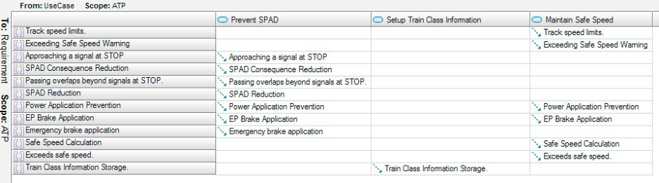
Requirements are grouped into Use Cases by means of dependency relationships, stereotyped ‘trace’ to distinguish them from other types of traceability link. These dependencies are typically added using matrix views (figure 4)
Figure 4: Use Case to Requirement Traceability Matrix
Functional Analysis Functional Analysis then proceeds by modeling each Use Case separately (these Functional Use Case Models are brought back together during the Design Synthesis phase). Use Cases are modeled with four distinct views using four different SysML diagrams:
Model Context (Internal Block Diagram)
Activity View (Activity Diagrams)
Scenario View (Sequence Diagrams)
State View (State Machine Diagrams) Each view contributes a different perspective to the system as a whole and it is important that consistency be maintained between them.
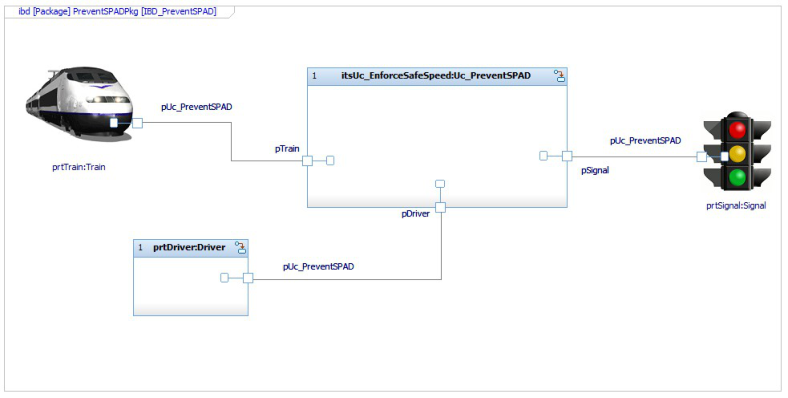
Model Context The Model Context view consists of a structural representation of the Use Case being modeled, along with any connected external entities (Actors).
Figure 5: Model Context
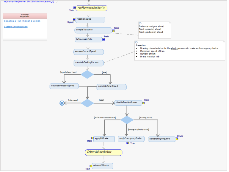
Activity View The Activity View models each of the potential high level functional flows using a single view – although there may be multiple Activity Diagrams for complex systems. Each action on the diagram is an operation of the system that may later be allocated to architecture – or is functionally decomposed (and allocated).
Figure 6: Activity View
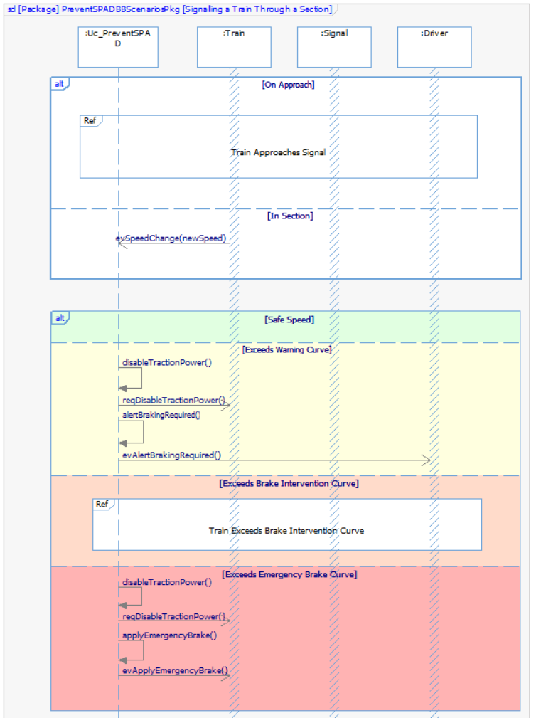
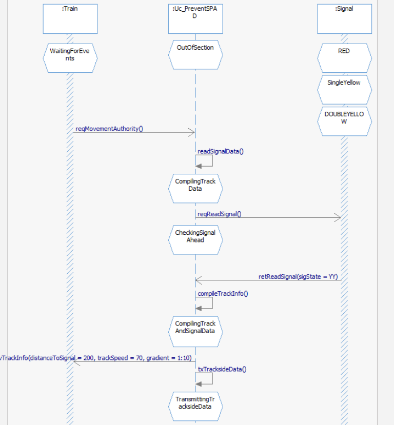
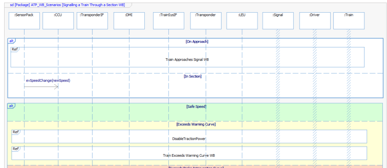
Scenario View The Activity View models all functional flows in one view. Each path through those potential flows is a scenario. SysML Sequence Diagrams show individual scenarios, which are useful for understanding and also form test cases. Moreover the focus for the Sequence Diagram is on the communication – rather than the internal operations of the system – which is the focus for the Activity View. However since the two views show some common information it is possible to auto-generate the scenarios through analysis of the Activity View.
Figure 7: Scenario View
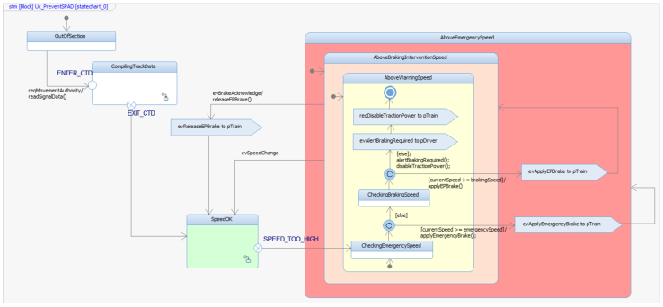
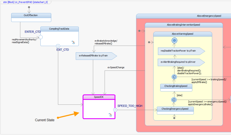
State View The actual behavior of the system is modeled using a SysML State Machine. Whilst an initial set of states may be derived from analysis of the Scenario Views, this view represents the domain knowledge of the modeler and as such requires human consideration.
Figure 8: State Machine
Model Execution One of the benefits of model based systems engineering is the ability to gain early confidence in the requirements or design through execution of the corresponding model. For example during the first execution of this model, the following issues were discovered:
In our design, the traction power was not disabled when it should be
Missing requirement: What to do if either emergency or EP brakes fail?
Missing requirement: Once emergency brakes have been applied, should they stay on until a safe speed is reached or should they switch to EP?
Figure 9: Model Execution - Animated State MachineFigure 10: Model Execution - Animated Sequence Diagram
Traceability of System Operations Once a sufficient level of confidence in the model has been reached, the system operations are traced back to the system requirements – this time using a dependency stereotyped ‘satisfy’. This technique allows gap analysis – are there any system operations that are not satisfying a requirement? or requirements that are not satisfied by an operation of the system? When operations are allocated later during Design Synthesis – this traceability propagates – effectively allowing an efficient way to allocate system requirements to architecture.
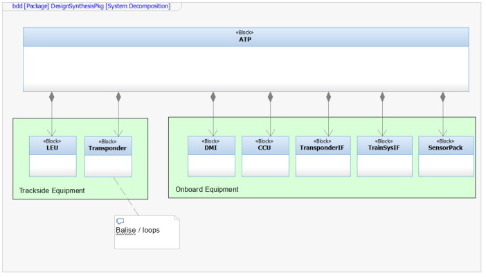
Design Synthesis Once the Functional Use Case Model has reached a stable baseline and its associated requirements have been verified and validated through model execution, the operations, attributes and external events may be allocated to architecture. The selection of architecture is usually influenced by a trade study, which is outside the scope of this paper and covered in detail in both the Harmony Deskbook (ref 1) and another paper, Getting the most from System Engineering Trade Studies using Model Driven Analysis with SysML Parametric Diagram Execution (ref 2). Once selected, the architecture is modeled using a SysML Block Definition Diagram:
Figure 11: System Architecture Modeled with Block Definition Diagram
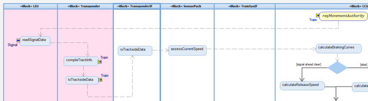
Allocation of Function to Structure The system operations may now be allocated from the Functional Use Case Model to the architectural pieces modeled on the Block Definition Diagram. The allocation strategy may be enacted using a ‘white box’ version of the original ‘black box’ Activity View – by splitting the view into Swimlanes. Each swimlane represents an architectural element and operations may be allocated simply by dragging them into the appropriate swimlane.
Figure 12: Allocation via Activity View (partial)
This ‘white box’ activity view provides a second benefit – generation of Sequence Diagrams – just as in the original black box view.
Figure 13: White Box Scenario View
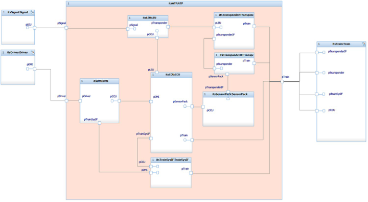
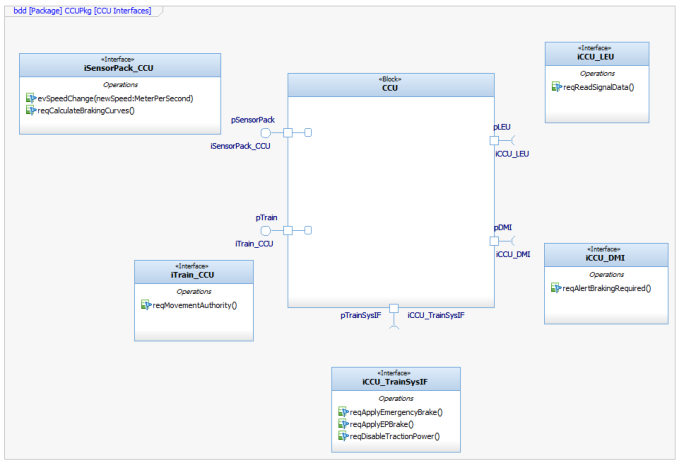
Interfaces Sequence Diagrams themselves give a benefit above the visualization, understanding and use as test cases. Since the focus for the diagram is on the communication between the lifelines represented on the diagram – they may be used to generate the interfaces between them also. This automatic generation ensures a robust definition of interfaces that is consistent and ‘minimal’ – that is the interfaces only contain the messages that need to be there. In SysML, interfaces are encapsulated in ‘ports’ along the boundary of an architectural element. Ports may then be connected together allowing the architectural elements to communicate.
Figure 14: Ports shown on an Internal Block DiagramFigure 15: CCU Subsystem Interfaces Shown on a Block Definition Diagram
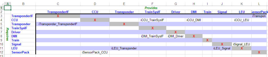
Further artefacts may be automatically generated from the existing model elements – for example allocation documents or classical N2 views.
Figure 16: Auto-generated N2 view
Subsystem State Machines and Model Execution The behavior of each subsystem is then modeled using a SysML State Machine – and the entire architectural model may be verified and validated through model execution. The resulting model contains a set of packaged artifacts for each subsystem that shows the requirements allocated to that subsystem, it’s interfaces and how it should behave – in short a model-based subsystem specification that may be handed off to another team to implement / further elaborate.
CONCLUSION
This paper presented how you can apply SysML modeling and analysis techniques to railway signaling systems. The paper presented the overall workflow and then showed with an example how the workflow is realized. The paper showed the key SysML views and artefacts used in the workflow – the same set of artefacts being re-used at Computing, Software, and Systems Engineering (2018) different levels of abstraction in a repeatable pattern. Model assets are re-usable and can be re-used in similar or subsequent projects allowing strategic re-use. Additionally, when a model is used, it can be quickly changed and modified to see and understand ramifications of a design change – or a change to the requirements. The techniques presented here provide real value to the design, implementation and testing of complex railway signaling systems, de-risking projects and saving a significant amount of development time and costs.
REFERENCES
Bleakley, G., Lapping, A. & Whitfield, A. (2011), Getting the most from System Engineering Trade Studies using Model Driven Analysis with SysML Parametric Diagram Execution, INCOSE International Symposium. Hoffmann, Hans-Peter (2014), IBM Rational Harmony Deskbook, version 4.1 Hoffmann, Hans-Peter (2006), “SysML-Based Systems Engineering Using a Model-Driven Development
Approach,” Proceedings of INCOSE 2006 International Symposium, Orlando, FL. OSLC Transitions Standards Development to International Standards Consortium, 2013
LISTED IN THE AHFE DIGITAL BOOKSTORE CATALOGUE
Explore the complete digital volume
Advances in Human Factors, Software, and Systems Engineering
Read this individual research paper free through the original publisher, or explore the full digital proceedings book.
ISBN 978-1-4951-2096-1
Explore this ISBN in the AHFE Bookstore ↗Listed in the July 2026 bookstore catalogue; search by ISBN to confirm current availability · Digital book purchase optional