Peter Gust, Aydin Ünlü (2022). Comfort Optimization Method for Work Equipment Based on a Digital Hand Model. In: Advances in Ergonomics In Design, Usability & Special Populations: Part II. AHFE Open Access, vol. 19. https://doi.org/10.54941/ahfe1001240
Comfort optimization for work equipment handles frequently fails in practice because of high temporal complexity and high development costs, coupled with the pressure of shorter development times. Handle design also has a strong subjective element rooted in the communication of comfort as sensation. Finally, handle design lacks an objective method to make comfort measurable. This paper presents a new method for achieving comfort optimization of work equipment based on a digital hand model, using the example of an iron bender. After determining significant factors of the work equipment, a so-called work equipment dependent pressure discomfort model (PDT model) is derived. The paper then focuses on practical creation of a finite element method (FEM) hand model. Finally, handle design parameters such as shape, size, material and surface can be derived from the FEM hand model in relation to the PDT model.
The human hand is constantly in contact with products. In particular, the handle of work equipment, as a direct interface to the user, greatly influences the perception of fatigue, pain and comfort (Lindqvist, 2008). The designer's job during handle development is to design handles that can be felt by the users to be comfortable. Comfortable handles need right decisions regarding handle design parameters such as shape, size, material and surface. In addition, the designer must consider many factors such as grip types, coupling types and target groups (Strasser et al., 2008).
Ergonomic handle design entails a methodical and systematic consideration of all important factors. The designer must always perform a rough and a fine analysis and question all conditions and factors that may finally have an impact on the design (Bullinger et al., 1979). The rough analysis is about the investigation of body position and movement possibilities, and motion assignment. The fine analysis is about the investigation of gripping types (crush grip, pinch grip, support grip), coupling types (form and force closure), and hand position (neutral or non-neutral). Design parameters will finally be determined by considering all these factors, with the help of guidelines about e.g. hand anthropometry (Strasser, 2011).
Ergonomic handle design also generally entails using many subjects for the evaluation of prototypes. This evaluation is purely subjective, and justifiably so, as handle design has a strong subjective element rooted in the communication of comfort as sensation. But this also causes high development costs and development times.
Handle design lacks an objective method for making comfort measurable. Take for example the case of vehicle seat comfort. A seat can be checked for comfortable pressure distribution and can be compared with other seats (Hartung, 2006). Thus the seat design can be objectively improved. It is also possible with FEM simulation to predict the discomfort of sitting and to improve on the CAD model (Mergl, 2006).
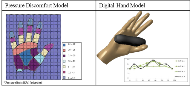
Research indicates that pressure distribution while gripping has a major impact on discomfort (Kuijt-Eversa, 2007). The aim is, therefore, to develop an objective method for comfort evaluation of work equipment, based on a digital hand model, taking into consideration pressure discomfort models in handle design (see Figure 1). With this new method, the constructor should already receive information on the CAD model about handle design parameters for the design of comfortable work equipment grips, thus enabling the number of test subjects and expensive prototypes to be reduced.
Pressure effect When a pressure acts on the skin over a longer period of time, the blood vessels dilate to maximize blood flow. This is shown by the increasing redness of the skin. After a while a second stage begins, where the blood starts to coagulate in the capillaries. If tissue deformation limits are exceeded, inhibition of the blood flow in the tissue occurs. This may in the worst case lead to cell destruction and an associated release of toxic substances that stimulate pain. Pain occurs when the body’s trained nociceptors signal that tissue-damaging stimuli noxious to the human body are acting (Murray, et al., 2001).
Dents in the range of 0.01 mm already evoke sensations of pressure in the palm. Tissue damage can occur if more significant localized pressure is applied. Thus pressure applied from 0.42 to 0.5 N/cm² for a duration of 2.5 minutes can result in a pressure collapse or obstruction of the blood flow (Hartung, 2006). However, with interim relief of the skin, higher pressures are tolerable.
Bennet et al. (1979) found that with high shear forces only half the pressure is required to occlude blood flow. The results relate to an area on the back of the hand, but appear to be transferable in principle to the palm. Goosens (1994) observations on the sacrum in young healthy subjects record hypoperfusion following 1.16 N/cm ² of pure compression. Moreover, a shearing load of 0.31 N/cm² is already equivalent to a pressure load of 0.87 N/cm² and is sufficient to cause critical constriction of the blood flow.
In addition, adaptation behavior comes into play in relation to pressure stimulus level and duration. A distinction is made here between very fast, medium-fast and slowly adapting receptors. Schmidt (1977) applied three pressure stimulus levels of 995g, 525g, and 155g on the skin and measured the receptor discharge (Imp/s) over a time of just 40 seconds. He found adaptation of the pressure receptors to pressure stimulus. For example, receptor discharge converged from 100 Imp/s to 10 Imp/s.
Pressure discomfort model A pressure discomfort model is derived from subjective ratings and objective pressure values (Hartung, 2006 p. 22). Pressure values are referred to as pressure discomfort thresholds (PDTs) (Aldiena et al., 2005). The term discomfort stands in relation to biomechanical and fatigue factors (Zhang, et al., 1996). Another key parameter is pressure pain thresholds (PPTs). PPTs describe the level of pressure that is perceived by the subject as painful (Rodday et al., 2011).
Based on this pressure pain research, Hall et al. (1993) examined the PPT of 64 skin areas and showed that the heel of the hand and the fold of skin between the thumb and index finger are sensitive to pressure. Figure 2 shows a section of the PPT of the palm. Further pressure pain investigations were carried out by Stevens et al. (1959) and Brennum et al. (1989). Women generally had significantly lower PPTs than men. The PPTs were mostly performed with a pressure algometer. But PPTs vary considerably in different publications depending on the methodology, the anatomical region of the pressure surface and the pressure increase. In addition a dependency of pressure sensation in relation to the form, size and material of the pressure stamp has been shown (Hall, et al., 1993).
The designer basically has to fall back on the PDTs of Hall et al. (1993) and Johansson et al. (1999). In the work of Johannson et al. (1999) the PDTs for three points of the palm were determined by pressure stamp. The results show that the index finger, the center of the hand area and the thumb have different sensations, and the thumb as opposed to the index finger and the center of the hand area is more sensitive to pressure. The PDT for the middle finger is 188 kPa, for the center of the hand area is 200 kPa, and for the thumb is 100 kPa. Using color subtractive printing films (Prescale) Hall also identified a PDT of 104 kPa for the entire palm (Hall et al., 1993). Overall, Lindqvist et al. (2008) recommended a uniformly distributed pressure distribution of 200 kPa on the palm as a rule for work equipment.
Work equipment handles produce different pressures on the palm depending on time. Thus the existing PDT, which lies between 100 kPa and 200 kPa, cannot be used to rate handle comfort. For example, handles that produce long- term pressures on the palm below 100 kPa will always be comfortable (e. g. vacuum cleaner handle), and handles that produce a short-term or pulsed pressure of about 200 kPa on the palm will always be uncomfortable (e. g. hammer handle). Also for handles that produce shear forces or vibration on the palm surface, established PDTs are irrelevant, because these factors can raise the pressure sensation (Bennet et al., 1979).
Digital hand model Digital hand models are generated by computer representations of the hand and can be simulated using either the multibody systems method (MBS) or the finite element method (FEM). It is also now possible to couple the methods of FEM and MBS together. In contrast to MBS models, FEM models are deformable and can calculate mechanical stresses such as pressure in certain parts of the body. MBS models consist of rigid non-deformable bodies connected to one another by kinematic joints. Using the MBS method, it is only possible to determine the kinematics of the body and the contact forces. These data are used for example, as input data for FEM simulation (Merten, 2008 p. 45ff).
Numerous digital human models that reflect the human hand as commercial software packages are already available. MBS models are primarily used in RAMSIS and ANYBODY to support ergonomic design optimization processes. An example of a coupled FEM / MBS human model is MADYMO, which was developed primarily for simulating crash tests. The data from MADYMO come from the human model HUMOS (Keppler, 2003 p 10f). Material properties relevant for hand models, such as density, Young's modulus, and Poisson's ratio for bone, skin, muscle, and tendons, are also known.
Other digital hand models focus on realistic simulation. For example, Wu (2012) developed a combined FEM and MBS finger model of three finger segments with realistic bones, nails and soft tissue. In the course of validation, pressure distribution in relation to handle stiffness and changes in geometry was simulated (Wu et al., 2005). Han et al. (2008) developed an FEM fingertip and simulated the pressure distribution on the fingertip when opening can tabs. The results revealed that over a large contact area pressure distribution was reduced to the fingertip. Xie et al. (2013) presented a static FEM hand model for the simulation of non-linear contact deformations, in particular in relation to realistic overlapping of the skin.
METHOD
The objective method was developed using an iron bender as application example. An iron bender is a hand tool for bending iron. When bending, the worker is physically stressed and feels pain on the palm after prolonged use. In the worst case, this can cause blisters and redness on the palm that impair the health of the worker.
Work equipment dependent pressure discomfort model To bend iron, the worker (usually male) as a rule uses the right hand to press the lever and the left hand to hold the iron. Therefore, it is a closed kinematic chain (dual wielding). The working movement extends approximately 60° with respect to the frontal plane. The bending is usually performed in a standing position. The bending process takes about 3 seconds, and one iron is bent per minute. To transmit a high force, the bending handle is gripped with a crush grip. The grip presses against the palm in a form fit, with neutral hand position. To bend an iron, an average bending force of 200N, determined with a load cell, is required.
Pressure distribution between the palm and three printed handles was measured with 6 FSR (Force Sensing Resistors). Their output voltages were recorded with PLX-DAQ (Data Acquisition Parallax tool) and were calculated by means of approximation functions. The three handles, with the same surface roughness and stiffness, varied in relation to the mean radius (minimum R = 12 mm, medium R = 16 mm, maximum R = 18 mm). These were attached to the handle of the drill stand.
A comfort multiplier of 9.43% for the palm was determined from the ratio between the average pressure values and the PPT of Hall et al. (1993). Finally, the pressure discomfort model for the iron bender was determined from the PPT of Hall et al. (1993) and the work-equipment dependent comfort multiplier.
FEM hand model The skeleton model of the hand was derived from the biomechanical human model "OpenSim" and adjusted to a 50th percentile man. For the determination of the outer contour of the undeformed human hand the data of "MakeHuman" were available. Starting from point clouds, the CAD software CATIA V5 (Dassault Systèmes, IBM) was used to produce solid models of the hand and bones. The positioning of the bones within the hand contour was based on computed tomography images of a man under the "Visible Human Project". Finally, the skeleton model was subtracted from the soft tissue geometry. Furthermore, crosslinking of the hand model in 3D tetrahedral elements was carried out.
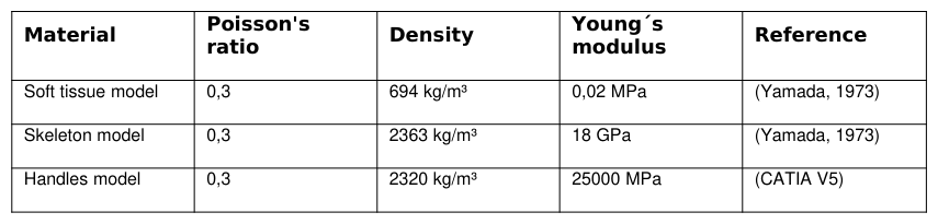
Because only one force direction was crucial for the application, an isotropic material behavior was chosen as a simplification. It is known from the literature that the behavior of human tissue is non-linear. But the investigation of Robin (2001) shows in MADYMO Release (2010) a linear material behavior of the hand tissue, for an application of max. 200kPa. Therefore, a linear material model was chosen for modeling. Since the fabric, according to the load, always returns to its original shape, the material behavior is modeled as elastic. Human tissue is therefore simplified for the model to be isotropic, linear and elastic. The handles defined as a silicon resin compound. Table 1 shows the material properties.
Boundary conditions were taken to be the contact conditions between the skeletal and soft tissue model and the handle surface. The handle was placed in the correct position on the hand surface, as in standard tests. For optimization, the handle with the lowest pressure values was selected as reference geometry. Optimum geometry and dimensions were found by manually modifying the shape of the handle.
Table 1: Material properties
RESULTS
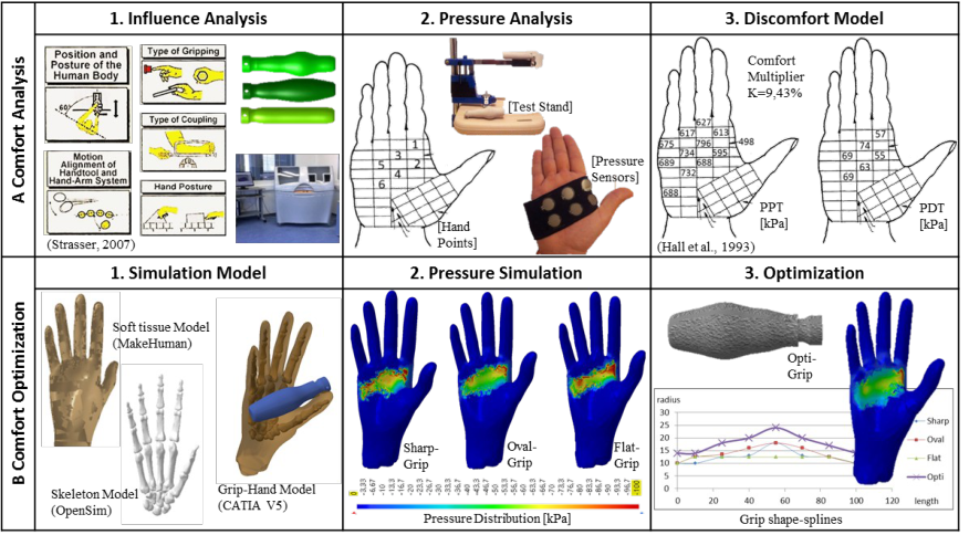
The comfort optimization method for work equipment based on a digital hand model is derived from the example of an iron bender. It comprises both comfort analysis and comfort optimization. Figure 2 shows the individual work packages of the method.
The aim of comfort analysis is to derive a work-equipment-dependent pressure discomfort model (PDT model) for the palm of the hand. The first step in determining the PDT model is to define and analyze the significant variables influencing the work equipment on the hand side and work side. Hand-side factors include gripping and coupling type, hand and body posture, but also hand types. Work-side factors include the level of force and force direction, as well as the kinematics of the applied force. Secondly, pressure distributions between grip and palm have to be measured in relation to varying handle design parameters. From the pressure distributions and the pressure pain threshold (PPT) of the palm as measured, a work-equipment-dependent multiplier can be determined. Subsequently, this multiplier can be used to transform the PPT values to the PDT values. The difference between PPT and PDT gives the tolerance range of upper and lower pain thresholds. The lower pain threshold is the so-called pressure discomfort threshold (PDT), which is work-equipment dependent. Embedded in a discomfort model, this PDT can already be used as a guideline for the evaluation of pressure distribution for gripping, so that the designer can decide after a few minutes how the handle will feel after several hours.
Grip comfort optimization is thus derived from a work-equipment-dependent PDT model based on a digital hand model. For this purpose, a simulation model of the human hand must first be created. This can be derived in the form of a skeleton model from open source programs such as "OpenSim", and in the form of a soft tissue model from "MakeHuman", and these models can be scaled in a CAD program such as CATIA V5 to the desired hand sizes. The simulation model must also reflect the information from hand-side and work-side comfort analysis. Manipulations such as gripping and coupling types, as well as hand position, must be transferred to the CAD system. After proper positioning of the grip on the palm, and the definition of boundary conditions such as contact and load conditions, the entire range of parameters can be meshed into a single model. Grip comfort optimization can finally be performed by varying different handle design parameters and checking the PDT borders. The aim is to bring the pressure peaks below pressure discomfort thresholds.
From the example of the iron bender it can be seen that hand point 3 has a low pressure sensitivity of 74 kPa. By varying handle shape, the pressure on hand point 3 was reduced to approximately 55kPa. Furthermore the pressure between the forefinger and thumb should be reduced, for example, by increasing the softness of the covering material.
Figure 2. Comfort optimization method for work equipment based on a digital hand model
DISCUSSION
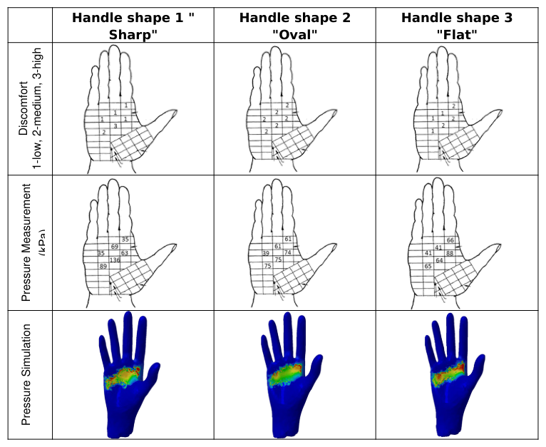
The work-equipment-dependent discomfort model (PDT) in Figure 2 was investigated with four male subjects between 27-45 years of age. For this purpose, three handles were attached to the handle of the drill stand. The subjects had to press the handles for a total of 3 minutes. The handles were pressed approximately with 200N and held for 3 sec., resulting in 12 pressure actuations per minute and a total of 36 actuations. The discomfort sensation was then evaluated for the six hand points. The evaluation was conducted on a scale of 1 to 3 (3 = high, 2 = medium and 1 = low discomfort sensation). The subjects were previously instructed about the relevant factors and were obligated to comply with them. However, in the experiments the influence of variables such as body position, grip type, hand position and force transmission were also checked.
Table 2 shows the measurement results for pressure distribution and discomfort evaluation with respect to all three types of handle. Overall high discomfort can be seen in relation to hand positions when pressure distribution lies above the PDT. High discomfort was created in handle shape 1 of hand point 4, as shown by the pressure measurement of 136 kPa, along with a significant excess of PDT at 63kPa. If the pressure distribution was below a PDT, the affected hand point was evaluated as experiencing little discomfort. It is also recognizable that at hand point 5 pressure distribution lay within the PDT values for all handles. At pressures with a slight deviation from the PDT, the affected hand point was evaluated as experiencing moderate discomfort. For example, a uniform distribution of pressure was felt in handle shape 2, where pressure distribution showed a slight deviation from the PDT.
The simulation results shows red spots at a pressure above 100 kPa. It can be clearly seen that a flat handle causes a pressure increase between the thumb and index finger. Also a sharp handle causes a high pressure value in the middle of the hand surface. The oval handle is comfortable after the simulation, because pressure distribution is below PDT values at hand point 2 and 5. This geometry was selected as the reference model for optimization. Optimization required five pressure simulations and geometry variations to reduce the pressure below the PDT value at hand point 5. The pressure at hand point 2 could not be reduced by changing the geometry. Here a softer material should to be chosen. It is recommended that these steps be programmed in future by an optimization algorithm. The pressures as measured were achieved overall in spite of the simplified geometry and material properties.
Table 2: Validation of the method Handle shape 1 " Handle shape 2
CONCLUSIONS
The comfort evaluation method developed in this research project by means of the work-equipment dependent discomfort model (PDT) is an effective tool for assessing handle shape. The method was applied using the example of an iron bender with three different handles. First the factors influencing the work equipment were analyzed and determined. Pressure distributions were then measured on the palm in relation to three handle shapes, using the defined factors. From the average pressure distribution of the work equipment on the palm, and using the PPT from Hall et al. (1993), a comfort multiplier and a discomfort model (PDT) were derived. The results show that exceeding the PDT produces high discomfort and falling below the PDT produces less discomfort in the subjects. It may, therefore, be concluded that the discomfort model with defined factors can be used for evaluating comfort in using an iron bender and similar tools, and that handle shape can be designed by applying the discomfort model (PDT) to create a more comfortable grip.
The remaining handle design parameters – dimensions, material and surface – are still to be investigated in relation to the PDT, and the impact on discomfort and pressure distribution of varying those parameters remains to be clarified. It may turn out that the main determinant of pressure distribution, and thus discomfort, is variation of shape. In this case a PDT model will depend in practice on shape variation.
In addition, the shear forces that occur during the use of work equipment should be included in the comfort multiplier. For the iron bender, shear forces could be neglected, as pressure distribution mostly arose in the palm. But screwdrivers, for example, inevitably generate shear forces on the palm, which may affect the pressure sensation to a high degree (Bennet et al., 1979).
Further studies must be performed with respect to age-related factors among elderly people. Currently, there are no PPTs of subjects over the age of 60. It has been found that, because of the lowering of sensitivity associated with aging, older people perceive pressure difference less acutely (Zenk, 2008). Other age-related factors include the reduction of the friction coefficient of the hand surface and the reduction of muscle strength and fat. Further research is needed into the role played by these changes for the PDT model, by investigating, for example, whether older people have a higher or lower PPT and PDT.
For the development of the simulation model, the principle was to reproduce the overall behavior of human tissue (including muscles, tendons, connective tissue, etc.) and material as easily and accurately as possible. The occurrence of processes and interactions in tissues or between muscles was disregarded: only the bones and surrounding tissue were modeled, as two separate entities, without reproducing internal structures. This procedure reduced possible sources of error, as well as high computation time. In future, the simulation model should approximate reality more closely, in order to calculate pressure distributions more accurately. In addition, a coupled MBS/FEM hand model is desirable in order to include gripping force and frictional forces in the pressure simulation.
The overall aim of the research is to program an ergonomics software "Comfortyping" using a readily available hand model. The user should, after importing the handle, choice of influence factors and PDT values, be able to derive proposals for handle design parameters: for example, spline proposals, which can then be imported into the CAD system. Such a program requires a database of different variables such as grip types and gripping forces, as well as hand-type and hand-position-dependent material properties. The program should offer a choice of three hand types with low, medium, and high levels of subcutaneous fat. In addition, it should scale the hand models independently by percentile and gender. By means of a "snapping" function, the hand model should automatically grip the tool handle.
REFERENCES
Aldiena, Y., Welcome, D., Rakheja, S., Dongb, R., & Boileauc, P.-E. (2005). “Contact pressure distribution at hand–handle interface: role of hand forces and handle size”. International Journal of Industrial Ergonomics 35. Bennet, L., Kaviner, D., Lee, B. K., & Trainfor, F. (1979). “Shear vs Pressure as Causative Factors in Skin Blood Flow
Occlusion”. in Arch Phys Med Rehabil Vol. 60. pp. 309-314. Brennum, J., Kjeldsen, M., Jensen, K., Jensen, & T.S. (1989). “Measurements of human pressure-pain thresholds on fingers and toes”. Copenhagen (Denmark): Elsevier. Bullinger, H.-J., & Solf, J. (1979). “Ergonomische Arbeitsmittelgestaltung - 2. Handgeführte Werkzeuge : Fallstudien“.
Frankfurt: Bundesanstalt für Arbeitssicherheit und Unfallforschung. Bystrom, S., Hall, C., Welander, T., & Kilbom, A. (1995). “Clinival disorders and pressure-pain threshold of the forearm and hand among automobile assembly line workers”. Volvo Car Corporation, Gothenburg, Sweden: Journal of Hand Surgery. Hall, C. F., & Kilbom, A. E. (1993). “Sensitivity of the hand to surface pressure”. Applied Ergonomics. Hartung, J. (2006). “Objektivierung des statischen Sitzkomforts auf Fahrzeugsitzen durch die Kontaktkräfte zwischen Mensch und
Sitz“. München: Lehrstuhl für Ergonomie der Technischen Universität München. Han, J., Nishiyama, S., Yamazaki, K., & Itoh, R. (2008). “Ergonomic design of beverage can lift tabs based on numerical evaluations of fingertip discomfort”. Japan: Applied Ergonomics. Johannson, L. K., Kilbo, A., & Hagg, G. (1999). “Perception of surface pressure applied to the hand”. In Ergonomics. London. Keppler, V. (2003). “Biomechanische Modellbildung zur Simulation zweier Mensch-Maschinen-Schnittstellen“. Tübingen:
Eberhard-Karls-Universität zu Tübingen. Kuijt-Evers, d. L. (2007). “Comfort in Using Hand Tools Theory, Design and Evaluation”. Delft: Technische Universiteit Delft. Lindqvist, B. (2008). “Ergonomie bei Handwerkzeugen“. Atlas-Copco-Drucksache. Mergl, C. (2006). “Entwicklung eines Verfahrens zur Optimierung des Sitzkomforts auf Automobilsitzen“. München: Lehrstuhl für Ergonomie. Murray, L., Magazinovic, N., & Stacey, M. (2001). “Clinical Practice Guidelines for the Prediction and Prevention of Pressure
Ulcers”. Clinical practice guidelines. Merten, v. K. (2008). “Verringrung des Risikos von thoraxverletzungen beim PKW-Sitenaufprall - FEM Simulationen mit dem Mensch-Modell HUMOS“. München: Ludwig-Maximilians-Universität München. N.N. (2010). “MADYMO Human Models Manual Release 7.2”. Developed at TNO MADYMO BV. Website:
https://www1.ethz.ch/biomed.ee/intranet/support/madymo/HumanModels.pdf Rodday, V., Geißler, B., & Ottersbach, H. J. (2011). Druckschmerzschwellen bei Druckreizen. Mainz: GfA. Robin, S. (2001). “HUMOS: Human model for safety – a joint effort towards the development of refined human-like car occupant models”. 17th International Technical Conference on the Enhanced Safety of Vehicles. Strasser, H., & Bullinger, H. (2008). “Handgeführte Werkzeuge und handbetätigte Stellteile“. Handbuch derArbeitsmedizin. Strasser. (2011). “Ergonomie bei der Gestaltung von Arbeitsmitteln“. Siegen: Institut für Arbeitswissenschaften. Strasser, H. (2007). “Assessment of the Ergonomic Quality of Hand-Held Tools and Computer Input Devices”. Amsterdam: IOS
Press, Ergonomics, Human factors and Safety, Vomule 1. Schmidt, R. (1977). “Grundriss der Sinnesphysiologie“. 3. Auflage: Springer. Stevens, J. C., & Mack, J. D. (1959). “Scales of apparent force”. Journal of Experimental Psychology 58. Wu, J. Z. (2012). “A Hybrid Model Simulating Hand Gripping on a Cylindrical Handle”. Morgantown. Wu, J. Z., & Dong, R. G. (2005). “Analysis of the contact interactions between fingertips and objects with different surface curvatures. In Proceedings of the Institution of Mechanical Engineers”, Part H: Journal of Engineering in Medicine 2005 219 89. National Institute for Occupational Safety and Health, Morgantown, West Virginia, USA. Xie, Y., Kanai, S., & Date, H. (2013). “Simulation of contact deformation property of Digital Hand skin and its experimental
verifications”. Sapporo, Japan: Graduate School of Information Science and Technology, Hokkaido University. Yamada, H. (1973). “Strength of biological materials”. Baltimore Maryland: Williams and Wilkins. Zenk, R. (2008). “Objektivierung des Sitzkomforts und seine automatische Anpassung“. Münschen: Herbert Utz Verlag. Zhang, L., Helander, M. G., & Drury, C. G. (1996). “Identifying Factors of Comfort and Discomfort in Sitting”. Human Factors: The Journal of the Human Factors and Ergonomics Society.
LISTED IN THE AHFE DIGITAL BOOKSTORE CATALOGUE
Explore the complete digital volume
Advances in Ergonomics In Design, Usability & Special Populations: Part II
Read this individual research paper free through the original publisher, or explore the full digital proceedings book.
ISBN 978-1-4951-2107-4
Explore this ISBN in the AHFE Bookstore ↗Listed in the July 2026 bookstore catalogue; search by ISBN to confirm current availability · Digital book purchase optional