Holly Hendry, Ana Cavalcanti, Cade Mccall, Mark Chattington (2023). Verification of a search-and-rescue drone with humans in the loop. In: Human Factors in Robots, Drones and Unmanned Systems. AHFE Open Access, vol. 93, pp. 110–120. https://doi.org/10.54941/ahfe1003753
In this presentation we use an example of a search-and-rescue drone, used by mountain rescue teams, to illustrate our approach to develop mathematical models and use them to verify behaviour that depends on human interactions with the drone. The design and development of human-in-the-loop robotic systems, such as the search-and-rescue drone, requires knowledge of the human, software, and hardware components of the system. The verification of these systems require knowledge of those same three components. Through this example we will demonstrate how a Hierarchical Task Analysis can be used to develop conformant sequence diagrams that can capture use cases of interest for verification. We will discuss the notation for our sequence diagrams, which is a variation of UML sequence diagrams tailored to capture time properties and with a view of the system that includes the software, the hardware, and human stakeholders.Our sequence diagram notation integrates within an existing verification framework, namely RoboStar, which provides domain-specific notations to model and verify both control software and robotic platforms. In the presentation, we show the kind of property and verification that we can carry out using our sequence diagrams and RoboStar technology. The presentation will also cover leading tools for modelling and verification of human-in-the-loop robotic systems, namely Circus, Ivy, PVSio-web and how they handle human behaviour within the system design. We will compare our approach with that supported by these tools.Verification is a technique used to prove that the system design and development meets the requirements specified; there are many forms of verification including formal verification, simulation, and testing. Formal verification is a tried and tested method to improve confidence in the correctness of a system, its ability to satisfy design requirements. Due to its application during design time, this confidence can be gained prior to the investing of time and resources into system development. Formal verification outputs mathematical proof artefacts that can be used in safety-case development. This verification technique requires formal models of system behaviour and formal models of the properties to be proved. To perform formal verification on a human-in-the-loop system, the formal model of the system behaviour needs to include a model of the expected human interaction. Whilst the data required for the generation of such a model can be provided by evidence from the fields of Human-Computer Interaction, Psychology, Human-Robot Interaction or Human Factors, this data needs to be gathered in a formal model for verification. On the other hand, requiring professionals with the knowledge of human behaviour to also have the expertise on formal verification is unrealistic. Our sequence diagrams are accessible and readable as a way to capture and communicate expected human behaviour. Moreover, it is possible to generate mathematical models for verification automatically from the sequence diagrams.
Verification of mobile and autonomous robotic systems has been a prevalent research topic within the last decade. It is a practice currently being explored in the field of Human-Robot Interaction to provide confidence in the cor- rectness of a system. Robotic systems with humans in the loop offer more opportunities for flexibility in the range of potential applications, but failure can arise from human behaviours. Yet rigorous verification in this setting is a challenge due to the complexity of human interactions. This is evident, for instance, for an autonomous vehicle in which the human stakeholders include passengers, other drivers, and pedestrians. Despite invested research in this area, there is little available for the verification of robotic systems with humans in the loop (Kress-Gazit et al., 2020).
To perform formal, mathematically founded, verification of a system inclu- ding humans in the loop, the formal model of the system behaviour needs to include a model of the expected human interactions (Bolton and Bass and Siminiceanu, 2013). Whilst the data required for the generation of such a model can be provided by evidence from the fields of Human-Computer
Verification of a Search-and-Rescue Drone With Humans in the Loop 111
Interaction, Psychology, Human-Robot Interaction or Human Factors, this data needs to be gathered in a formal model for verification. Requiring pro- fessionals with the knowledge of human behaviour to also have the expertise on formal verification required to create these models is unrealistic.
In this paper, we present a notation that is usable by various stakehol- ders in the robotic development lifecycle, including human factors engineers and roboticists. The notation is based upon sequence diagrams as they are a widely used, intuitive, and human-readable way to capture and communi- cate expected human behaviour (Al-Fedaghi, 2021). Moreover, it is possible to automatically generate mathematical models for formal verification from sequence diagrams written using our notation in order to prove properties of interest.
Here we illustrate our notation through its application in a search-and- rescue drone. The next section provides further detail on the drone case study. This is followed by a section giving an overview of our notation, justifying its design based on the user studies we have carried out, the case study as depicted in the notation, and its mathematical semantics. The verification of a key property of the search-and-rescue drone is outlined and discussed. Finally, we compare our approach to that of leading tools for modelling and verification of human-in-the-loop robotic systems, namely Circus (Martinie, 2022), Ivy (Campos, 2022), and PVSio-web (Masci and Oladimeji, 2022).
CASE STUDY The search-and-rescue (SAR) drone used as a case study is derived from cur- rent practices used by mountain-rescue teams in the Brecon Beacons. These practices, documented through onsite industrial research (Hart et al., 2020), depict the use of a drone and handheld interface to find a missing person through the execution of search patterns dependent upon the terrain in which the person disappeared.
A Hierarchical Task Analysis (HTA) has been generated for this case study. The HTA has been extended to include time constraints and expectations on tasks in the form of minimum and maximum wait times and action times. The HTA documents the tasks undertaken by the SAR team from the notification of a missing person through to the finding of said person using the SAR drone.
In-keeping with the Civil Aviation Authority regulations for the drone to be within line of sight during operation (Civil Aviation Authority, 2019), there are two humans present during the drone’s flight. The pilot directs the drone during manual flight, using a handheld controller, and visually monitors the drone during automated flight. The observer monitors the drone’s video feed for any sighting of the missing person, signalling to the pilot when to halt the search.
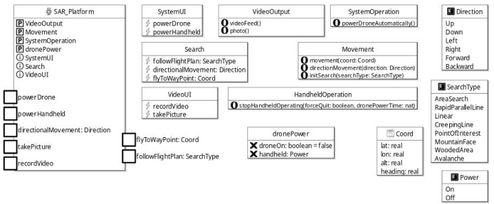
Software Model Modelling of the SAR software has been undertaken in RoboChart, a robotics modelling notation with mathematical foundations for use in formal verifi- cation (Miyazawa et al., 2019). Figure 1 shows both the SAR drone and both handheld controllers as a single robotic platform element, with user inputs,
Figure 1: Robotic platform, interfaces and types for the RoboChart model.
‘takePicture’, modelled as RoboChart events (denoted by lightning bolts) and system operations, ‘photo()’, modelled as RoboChart operations (an O).
The robotic platform, named SAR_Platform, indicates whether the plat- form takes interfaces as inputs (i) or provides (P) system operations for use. The input events are connected to system controllers via a module, where each controller has at least one state machine outlining the system execution. These state machines depict how the input events trigger execution resulting in operations being actioned. For example, the ‘recordVideo’ event in the ‘VideoUI’ interface is connected in the SAR Software module to the ‘Vide- oController’ which in turn is connected to the ‘VideoStateMachine’. Within the ‘VideoStateMachine’, the ‘recordVideo’ event triggers the actioning of the ‘videoFeed()’ operation through the ‘VideoOutput’ interface. This operation is only actioned on the condition that both the Handhelds and Drone are on, determined by the triggering of the ‘powerDrone’ and ‘powerHandheld’ events in the ‘SystemUI’ interface.
NOTATION This section first covers the requirements of our notation, followed by demonstrating its use in the SAR case study.
Requirements With the goal of identifying requirements for a modelling and verification notation specific for tele-operated robotic and autonomous systems, we have conducted a series of semi-structured interviews on existing approaches to including humans-in-the-loop in the development process. Participants (n = 14) were a variety of professionals working at various stages in the deve- lopment cycle of a robotic system. These professionals work in roles including human factors engineer, UX designer, software engineer, researcher and tech- nical director. The participants work at companies across sectors such as nuclear, defence, aerospace, maritime, manufacturing, lab automation, and the automotive industry. All participants were based in the UK and other Western European countries.
Verification of a Search-and-Rescue Drone With Humans in the Loop 113
Reports from these 8.5 hours of interviews span the spectrum from not considering human behaviour during design through to a fully specified process to identify and explore all possible points of human interaction within the system. Twenty-three tools, including Doors and Enterprise Arch- itect, were referenced and 12 standards, such as ISO, mentioned during the interviews. Alongside these, 19 design methods, like user stories and prototy- ping, and 14 key “human behaviours”, boredom being one, were identified through qualitative analysis of the interviews.
Our main conclusions are that processes used for tele-operated robotic system design, and the skills of those executing these processes, vary widely between companies and sectors. As such, any notation defined would need to be flexible and intuitive. In addition, to meet the requirement to support verification, it needs to be a precise and tractable notation.
Notation Syntax To ensure familiarity for users, we use a restricted UML sequence diagram notation enhanced to support modelling of human-centred systems. The notation is rich enough to express the kinds of properties we are interested in but can be given a mathematical semantics that is tractable. Distincti- vely, there are also additional constructs, wait and deadline, allowing for the description of time budgets and deadlines on interactions from human users.
To perform verification of system properties, we need to connect our sequence diagrams to the RoboChart diagram modelling the software and identifying robotic-platform requirements. The RoboChart model is platform independent, but as mentioned, defines the services used by the softw- are. Some of these may be means to support human interactions: a simple example is an on/off button represented by an input event in RoboChart, like ‘powerHandheld’. Such services need to be reflected in the sequence diagrams.
Being platform-independent, the RoboChart model abstracts the structure of the platform. For human-centred problems, however, the method that humans use to interact with the platform may play an important role in the clarification and understanding of the system execution. In the case of the SAR example, the platform is comprised of the drone and the handheld. Both need to be considered in our sequence diagram to improve the readability of the system flow.
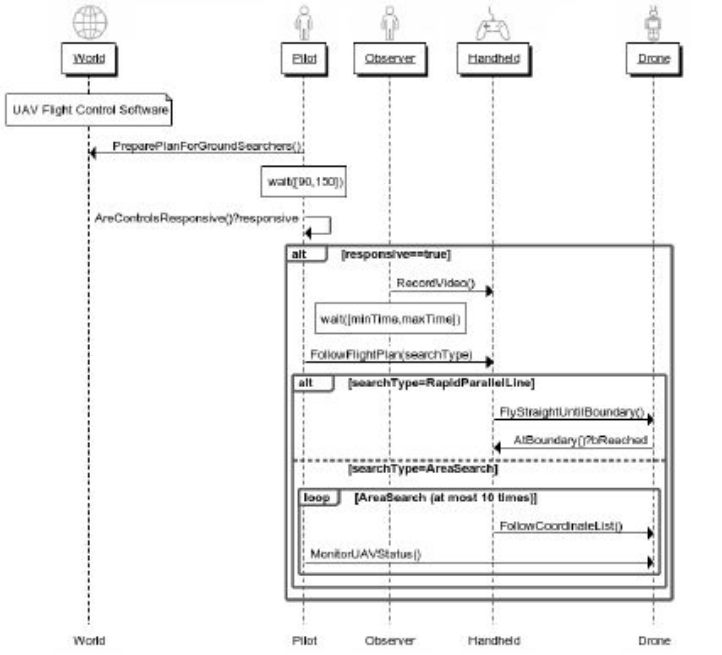
When using our sequence diagram notation, there must be lifelines for every piece of hardware the user can interact with, both in the form of inter- faces and physical robotic devices, for each of the human users, and one to represent the world. Figure 2 shows five actors and their associated lifelines, vertical parallel lines down which the ordering of actions can be specified, within the SAR example. These actors are differentiated via their symbols as either human (man icon), device (robot icon), interface (controller icon), or world (globe icon).
In this example, the ‘Observer’ and ‘Pilot’ actors are of type ‘Human’ while the ‘Handheld’ actor is of type ‘Interface’ and ‘Drone’ is of type ‘Device’. The
Figure 2: Subsection of the SAR case study for displaying notation constructs.
‘World’ actor represents anything outside of the system itself upon which the system may depend, such as external software. What the ‘World’ actor is depicting, at any given time, can be indicated through the use of comments; in the example, ‘UAV Flight Control Software’ is introduced as a comment. This form of construction has no effect on the diagram semantics, but improves readability.
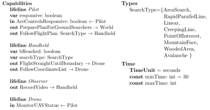
As with UML, interactions between actors are modelled as arrows in the direction the message is sent. For example, the pilot telling the drone to fol- low the flight plan, defined in variable ‘searchType’ of type ‘SearchType’, is modelled as an arrow from the ‘Pilot’ lifeline to the ‘Handheld’ lifeline with the message ‘FollowFlightPlan(searchType)’. This message is linked to the capabilities of the actors through an associated capabilities-and-variables document. An example of this can be seen in Figure 3 where the ‘Follo- wFlightPlan: SearchType -> Handheld’ capability is attached to the ‘Pilot’ as the initiator of the capability. This capability has an argument of type ‘SearchType’ and is output from the Pilot to the Handheld. Messages are considered instant, unless indicated otherwise through a wait.
The new wait construct can be used to model a time budget for the com- pletion of actions induced by the messages. The lifeline upon which the wait
Verification of a Search-and-Rescue Drone With Humans in the Loop 115
Figure 3: Example capabilities-and-variables document for the SAR case study.
is placed indicates the actor requires the specified time to complete the prior action. The TimeUnit to be used is defined alongside the capabilities decla- ration with possible values such as seconds, minutes and hours. In the SAR example, the message ‘TurnOnHandheldController’ is followed by a wait construct of ‘wait([90, 150])’ to indicate that the ‘Pilot’ actor can take a minimum of 90 time units and a maximum of 150 time units to complete their part in the actioning of ‘TurnOnHandheldController’. If the wait was for a specific time period, for example 90 time units, it could be added in the form ‘wait(90)’; it is unusual, however, for time budgets to be specific. The approach ‘wait([minTime, maxTime])’ can be used, in place of defini- tive values, where ‘minTime’ and ‘maxTime’ are defined as constants of type integer alongside the time unit declaration. The assignation of values to these constants being optional allows for the creation of the model prior to having knowledge of timings.
Human decision making, such as the ‘AreControlsResponsive’ capability on the ‘Pilot’ lifeline in Figure 2, is modelled through an arrow from the ‘Pilot’ lifeline to itself. These capabilities set the value of a variable of type boolean using the Message?variable structure. This means that the variable can be set with either a true or false value, and in this example said value is then used for the condition to determine different branches of the system execution.
Conditions, situations in which the sequence of actions may follow multiple branches, can be modelled through UML alt constructs attached to variable values. Use of this construct is shown in Figure 2 as a box around actions under the condition ‘responsive==true’ which, as stated above, is linked to the previous message, ‘AreControlsResponsive’, on the ‘Pilot’ lifeline in which the ‘responsive’ variable is assigned a value. The alt construct is associated with an else element that is shown through the ‘searchType==Area Search’ section of the flight plan alt box and is separa- ted from the ‘searchType==RapidParallelLine’ search sequence path with a dotted line. In the case of multiple possible conditions, more than one else element can be added to the alt construct.
Loops are used to encompass sets of messages that should be repeated, such as the method for undertaking an area search that requires the drone flying to each point in a list of coordinates while the ‘Pilot’ monitors its progress. For further tractability within our notation, constraints can be placed upon loop constructs. A constraint is visible in Figure 2 as ‘(at most 10 times)’ on the ‘Area Search’ loop. This prevents the loop from exceeding ten executions but indicates that there could be a case for the loop to exit prior to this, such as the missing person being found.
Messages sent between ‘Human’ actors and ‘Interface’ or ‘Device’ actors are connected to the RoboChart model through their capability definitions in the capabilities-and-variables document, either as input events or operation outputs. We can prove properties of the system dependent upon these capabi- lities, however for the ‘World’ actor we can only prove properties about time taken as we do not expand upon how the ‘World’ executes its capabilities. As stated previously, the ‘World’ lifeline represents anything with which the system interacts that exists outside of the system itself, ie. the scope of the model.
VERIFICATION Verification is a technique used to prove that a system design and behavi- our meet the requirements (Luckcuck et al., 2019). There are many forms of verification including formal verification, simulation, and testing. Formal verification is a tried and tested method to improve confidence in the corre- ctness of a system. Due to its application during design time, this confidence can be gained prior to the investing of time and resources into system deve- lopment. Formal verification provides mathematical proof artefacts that can be used in safety-case development (Butterworth, 1998). This verification technique, however, requires formal models of system behaviour and formal models of the properties to be proved.
For illustration of our work, this section defines a property of our case study that we will prove supports proof through formal verification. The semantics for our notation is briefly discussed prior to the property being proved.
Property of Interest A property of the SAR drone derived from existing system expectations is:
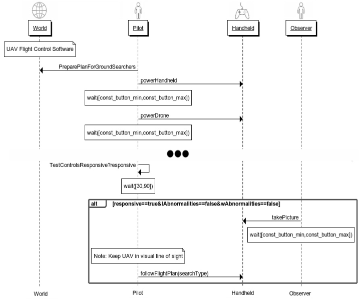
The drone should begin searching within ten minutes of being turned on. This property depends upon the hardware and software of the drone, the hardware and software of the handheld controller, the scenario in which the drone is flying, the pilot who is operating the drone, and the observer moni- toring the video feed. These elements are defined in the sequence diagram, Figure 4, and the RoboChart model, Figure 1, and as such both are required to prove this property.
Semantics To perform formal verification, any model defined needs to be translated into a verifiable format such as CSP (Woodcock et al., 2009). The semantics are
Verification of a Search-and-Rescue Drone With Humans in the Loop 117
Figure 4: Subsection of the SAR functionality upon which the property of interest depends, with ellipses representing hidden events.
the mathematical backbone of the notation allowing for such a translation to take place.
Both RoboChart and our sequence-diagram based notation have their own defined semantics in CSP. These semantics can be integrated and the conju- nction of the two models, expressed through parallel composition, provides the definition of the system for use in formal verification.
Proving the Property The generated CSP for the RoboChart SAR software model, and the hand- written CSP for the sequence-diagram based notation model, have been combined into a single process named SYSTEM. The property of interest has also been encoded in CSP. With these encodings, we can use FDR (Ábrahám and Havelund, 2014), a tool for CSP, to prove the property fully automati- cally. Future work will generate the semantics of the sequence diagram and the SYSTEM process automatically.
SpecP1 specifies the execution of three events, PreparePlanForGround- Searchers, powerHandheld and powerDrone, before entering a deadline constraint, as seen in Figure 5. This constraint states that after a powerDrone event, within the space of 600 seconds, an initSearchCall event must occur preceded by any combination of other events specified within a set ALL.
Figure 5: The specification and assertion for the property of interest in CSP.
Figure available in the original PDF paper.
Finally, once initSearch is called with any SearchType as an argument, the terminate event should be observed.
The assertion, on line 6 of Figure 5, checks that the property, SpecP1, traces refines the SYSTEM process. Traces refinement checks that each possible path through SYSTEM is contained within those defined by SpecP1. In this case, the assertion passes meaning the property holds.
However, should the property have stated 300 seconds, then the assertion would fail and FDR would display the counterexample. The refusals of the counterexample displays the cases in which the assertion would fail. In this case, the specification, SpecP1, does not allow time to proceed because a deadline has been reached, however the system still allows for more time to pass, therefore missing the deadline. Specifically, SpecP1 is expecting to see an initSearchCall event, but SYSTEM is 74s into the execution of the event TestControlsResponsive.
CONCLUSION
The approach and notation outlined in this paper is capable of proving properties about robotic systems that rely upon human interaction. This is demonstrated through the proof of a key property of our example. The system execution is verified as always being completed within ten minutes, taking into consideration both the wait times for human interaction defined in the sequence diagram and the execution times of the software as defined within the RoboChart model.
Through adapting the existing UML sequence diagram notation, we have created a notation, which is understandable for various stakeholders in the robotics development lifecycle, for the modelling of robotic systems with humans in the loop upon which properties can be proved through formal verification.
This approach differs from those employed by leading tools for modelling and verifying human-in-the-loop robotic systems: Circus (Martinie, 2022), Ivy (Campos, 2022), and PVSio-web (Masci and Oladimeji, 2022).
The HTA-like approach offered by Circus, in their HAMSTERS com- ponent, is entirely graphical, providing an easy to use interface and clear identification of user interactions. This approach does not have, however, any mathematical foundations to support formal verification.
Unlike Circus, both Ivy and PVSio-web have the mathematical foundations necessary for formal verification. IVY uses an action-logic textual notation that requires specialist knowledge, thereby not satisfying the requirement of a usable notation for non-roboticist stakeholders.
Verification of a Search-and-Rescue Drone With Humans in the Loop 119
PVSio-web is a prototyping tool in which prototypes can be connected to PVS models defining the functionality of the system. This approach allows for the gathering of user behaviour data through manual user testing on the pro- totype. However, the models of the system functionality, which can include user actions, require knowledge of PVS, or EmuCharts for simplified models, to generate. As with IVY, this requires specialist knowledge.
In the future we will mechanise the semantics of this notation, automa- ting the translation from our sequence-diagram notation to CSP. We will also consider the use of sequence diagrams to specify properties of the system (Windsor, 2022), in this way removing any need for knowledge of CSP by the users.
ACKNOWLEDGMENT
The authors would like to acknowledge the participants of the user research study in the Notation Requirements section. The work has been funded by the UK EPSRC Grants EP/R025479/1, and EP/V026801/2, by the UK Royal Academy of Engineering Grants No CiET1719/45 and IF2122\183, and by a Thales EPSRC iCASE Grant EP/W522296/1, Award No 2605294.
REFERENCES
Ábrahám, E. and Havelund, K. (eds) (2014) ‘FDR3 --- A Modern Refinement Checker for CSP’, in Tools and Algorithms for the Construction and Analysis of Systems. (Lecture Notes in Computer Science), pp. 187–201. Al-Fedaghi, S. (2021) ‘UML Sequence Diagram: An Alternative Model’, Internatio-
nal Journal of Advanced Computer Science and Applications (IJACSA), 12(5).doi: 10.14569/IJACSA.2021.0120576 Bolton, M. L., Bass, E. and Siminiceanu, R. (2013). ‘Using Formal Verification to Evaluate Human-Automation Interaction: A Review’, IEEE Transa- ctions on Systems, Man, and Cybernetics: Systems, 43(3), pp. 488–503. doi: 10.1109/TSMCA.2012.2210406. Butterworth, R., Blandford, A. and Duke, D. (1998) ‘The Role of Formal Proof
in Modelling Interactive Behaviour’, in: Markopoulos, P. and Johnson, P. (eds.) Design, Specification and Verification of Interactive Systems ‘98. Eurographics. Springer, Vienna. doi: 10.1007/978-3-7091-3693-5_7. Campos, J. (2022) IVY Workbench. Available at: http://ivy.di.uminho.pt/. Civil Aviation Authority. 2019. The Drone and Model Aircraft Code. [ONLINE] Available at: https://register-drones.caa.co.uk/drone-code/flying-safely-and-respo nsibly. [Accessed 9 January 2023]. Hart, S., Banks, V., Bullock, S., Noyes, J. (2022). ‘Understanding human decision-
making when controlling UAVs in a search and rescue application’, in Ahram, T. and Taiar, R. (eds.) Human Interaction & Emerging Technologies (IHIET 2022): Artificial Intelligence & Future Applications. AHFE (2022) Internatio- nal Conference. AHFE Open Access, vol 68. AHFE International, USA. doi: 10.54941/ahfe1002768 Kress-Gazit, H., Eder, K., Hoffman, G., Admoni, H., Argall, B., Ehlers, R., Heckman, C., Jansen, N. et al. (2020) ‘Formalizing and Guaranteeing* Human- Robot Interaction’, CoRR, abs/2006.16732. Available at: https://arxiv.org/abs/ 2006.16732.
Luckcuck, M., Farrell, M., Dennis, L., Dixon, C. and Fisher, M. (2019) ‘Formal Specification and Verification of Autonomous Robotic Systems: A Survey’, ACM Computer Survey, 52 (5), pp. 1–41. doi: 10.1145/3342355. Martinie, C. (2022) Circus Tool Suite. Available at: https://www.irit.fr/recherches/I
CS/softwares/circus/. Masci, P. and Oladimeji, P. (2022) PVSio-web. Available at: http://www.pvsioweb.o rg. Miyazawa, A. , Ribiero, P., Li, W., Cavalcanti, A, Timmis, J. and Woodcock, J. (2019)
‘RoboChart: modelling and verification of the functional behaviour of robotic applications’, Software & Systems Modeling, 18, pp. 1–53. doi: 10.1007/s10270- 018-00710-z. Windsor, M., Cavalcanti, A. (2022). ‘RoboCert: Property Specification in Robotics.’ in: Riesco, A., Zhang, M. (eds) Formal Methods and Software Engineering. ICFEM 2022. Lecture Notes in Computer Science, vol 13478. Springer, Cham. doi: 10.1007/978-3-031-17244-1_23. Woodcock, J., Larsen, P. G., Bicarregui, J. and Fitzgerald, J. (2009) ‘Formal Methods:
Practice and Experience’, ACM Computer Survey, 41 (4), pp. 1–36. doi: 10.1145/ 1592434.1592436.
LISTED IN THE AHFE DIGITAL BOOKSTORE CATALOGUE
Explore the complete digital volume
Human Factors in Robots, Drones and Unmanned Systems
Read this individual research paper free through the original publisher, or explore the full digital proceedings book.
ISBN 978-1-958651-69-8
Explore this ISBN in the AHFE Bookstore ↗Listed in the July 2026 bookstore catalogue; search by ISBN to confirm current availability · Digital book purchase optional