Vitus Lüntzel, Florian Schade, Martin Sommer, Eric Sax (2023). Modularized Platform for an Embedded Systems Case Study: Concept and Design. In: Human Interaction & Emerging Technologies (IHIET 2023): Artificial Intelligence & Future Applications. AHFE Open Access, vol. 111, pp. 840–848. https://doi.org/10.54941/ahfe1004092
This paper presents the concept and design of a hardware platform for an information technology workshop aimed at first-year electrical engineering students. The workshop provides students with their initial exposure to hardware-oriented programming and project management in a software engineering environment. The platform is centered around a Tiva C LaunchPad embedded on the control board of a remote-controlled vehicle. The hardware design of the remote vehicle is modularized into three boards: the control board, battery management board, and power management board. Additionally, a remote-control interface has been developed. The hardware platform leverages various capabilities of the Tiva C LaunchPad, including GPIO, ADC, PWM, and UART, although the I2C capabilities are not utilized in the workshop.Students work in groups of three to gain valuable project management experience. While each student is responsible for developing an individual hardware-related class, these classes are utilized for group tasks. To prevent complete group failure in case of one student's inability to finish their class, example classes are provided as usable libraries. The organization of responsibilities within the group is left to the students, and a project plan and Gantt chart timeline are mandatory.The hardware design adopts a modular structure that effectively separates main functions and power levels. The battery management board hosts the main fuse and an emergency shutdown relay, connected to a reed switch. It facilitates the connection between the batteries and the power management board. PWM signals from the control board on the power management board actuate two 12V brushless DC electric motors. Additional connections to the control board include a 5V power supply, a proportional measurement of the battery voltage, and control over the revolution speed of the drives. The control board, which houses the Tiva C LaunchPad, is also connected to ultrasonic sensors, an ESP8266-Module, and the power control board. The remote-control interface, featuring another Tiva C LaunchPad, facilitates human-machine interactions through an 8-bit display, a joystick, and navigation buttons. The remote control is powered by a 5V power bank.The software architecture also follows a modular approach, leveraging object-oriented programming principles. Seven different classes instantiate hardware-related functionalities. Additionally, four hardware-independent classes are employed. While all the functions of the remote-controlled vehicle are consolidated in one hardware-independent class, three are dedicated to remote control operation: Steering, responsible for reading joystick input and mapping it to commands; Display, enabling user output through an interactive menu; and Remote, serving as the central class that brings together low-level and other hardware-independent classes.In conclusion, this hardware platform offers first-year electrical engineering students a practical and comprehensive introduction to hardware-oriented programming and project management. The workshop provides students with hands-on exposure to industry-relevant technologies and a collaborative learning experience. The platform's integration of software and hardware components promotes a holistic understanding of systems engineering principles.
The practical application of learning contents is paramount in the educa- tion of electrical engineering students, not only due to the general disposition of putting theory into practice but potentially improving students’ soft skills alike (Jollands et al., 2012). While the traditional lectures provide the students with the theoretical foundations, project-based learning offers the opportunity to bridge the gap between theory and practice. The fac- ulty of Electrical Engineering and Information Technologies (ETIT) of the
Modularized Platform for an Embedded Systems Case Study: Concept and Design 841
Karlsruhe Institute of Technology (KIT) recognizes the need for objective- related laboratories across the bachelor’s degree program and has therefore designed a continuous mandatory workshop (Beuth et al., 2013). The work- shop spans the first four semesters and is attended in addition to lectures and theoretical exercises. For the duration of the workshop, the students are loaned several parts including but not limited to a DC motor, an ultrasonic sensor, LEDs, a Tiva LanchPad, and a breadboard.
At the Institut fuer Technik der Informationsverarbeitung (ITIV) the second-semester lecture Informationstechnik I is accompanied by the Informationstechnik I – Praktikum (PIT), a project laboratory in which stu- dents work on an embedded systems programming task (Beuth et al. 2015). The goal is to provide the student with a practical introduction to hardware- oriented programming and project management. The workshop contains a case study for embedded systems programming in which students work in teams of three to solve a programming problem. The problem mimics a real- world scenario, where a customer hires an external programming team to bring their hardware platform into service (Tradowsky et al., 2015). The stu- dents are tasked to fulfill given customer requirements in a timeframe of seven weeks and afterward present their software product. Within this timeframe, the team has to understand the tasks, acquaint themselves with hardware- oriented programming (guided by the accompanying lecture), distribute the tasks, create a timetable and project plan, and program and test the different functions of the platform.
The hardware platform is the central component of the task. While in the past a two-wheeled self-balanced vehicle was used as a platform for multiple laboratories at the ITIV, a new platform was chosen. The new platform, same as the old, was not only to be used for the PIT but poten- tially be modified to be used for other ITIV labs as well, of which an overview can be found in (Beuth et al., 2015). Due to the large number of students in the PIT i.e., over 350 participants per year, individual testing of each student’s code on the hardware platform was considered unfeasi- ble. Thus, a means to abstract it with the hardware provided by the ETIT workshop was required, posing additional demands on the design of the platform.
The F1TENTH is one example of a platform used in laboratories across different universities. It is used for example by the University of Pennsylvania for a 15-week course on autonomous driving (O’Kelly et al., 2019) or by TU Dortmund for teaching cyber-physical systems design (Ueter et al., 2020). While the idea of using a vehicle as a platform for teaching is con- vincing, the ITIV requires a system capable of high modularization and the possibility to exchange the different PCBs to facilitate multiple work- shops. Therefore, it was decided to develop an in-house solution for a remote-controlled vehicle. As a foundation, the Magni Silver™robot base by Ubiquity Robots was chosen, as its design supports loads of up to 100kg. Only the original chassis, wheel and motor assembly, and sonar array were retained, while all other parts were replaced with a custom hardware platform.
While (Tradowsky et al., 2015) describe the old laboratory in its struc- ture and evaluations, this paper focuses on the newly developed hardware platform. Therefore, the modular concept of the hardware platform is intro- duced and then the different components and their function on the PCBs are discussed in detail.
MODULAR HARDWARE PLATFORM The platform needs to fulfill a multitude of demands. The primary require- ments come from the case study itself and the ETIT workshop. Secondary requirements are set by the ITIV labs.
The case study is designed to pose programming tasks for students with little prior programming experience. They learn how to develop software for a microcontroller and work as a group in a structured way. On the one hand, simple, hardware-oriented classes, such as a PWM class, are to be included for each member of the team, as well as higher-level functions, that shall be implemented as a group. This results in the need for diverse, but simple usage of the microcontrollers capabilities on the platform. The ETIT workshops loans the required hardware for testing the code to the students for free. As it is fully sponsored, the costs of the parts required for testing should be low. High testability and low design complexity are additional requirements.
On the other hand, it should be designed for extensibility to fulfill the diverse needs of other laboratories. The design should prioritize high main- tainability and adaptability to accommodate potential changes, for example, a new microcontroller being used in the student workshop. Additional requirements for specific design decisions are posed by the laboratory circuit design, in which three PCBs with similar functionalities are to be designed and tested by master’s degree students.
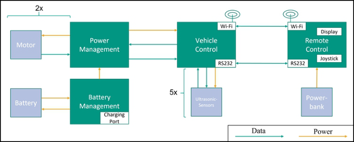
To fulfill these requirements, a modular architecture was designed. Figure 1 depicts four main components divided by their functions: Battery Management, Power Management, Vehicle Control, and Remote Control. All of them have interactions with the main and secondary parts. The Battery Management facilitates functionality related to the platform’s power supply i.e., battery charging, overcurrent protection, as well as an emer- gency shut-off. Power Management comprises the platform’s power sup- ply providing multiple voltage levels and its power electronics, interfacing the motors. Both of the PCBs can be reused by other labs with differ- ent vehicle controls. Vehicle Control generates the motor control signals based on control commands received from the Remote Control and envi- ronment information obtained from sensors. The Remote Control pro- vides a user interface that allows the user to issue control commands and obtain information on the vehicle status. It communicates with the Vehicle Control using either a wireless connection or, as a fallback solution, the RS232 protocol. While all other components are fixed on the chassis and powered by the main battery, the remote control is powered using a power bank.
Modularized Platform for an Embedded Systems Case Study: Concept and Design 843
Figure 1: Modular hardware concept of the platform.
Battery Management PCB The battery management PCB is designed to fulfill several battery-related functions. These are an overcurrent protection, a switchover between charg- ing and operational mode, and an emergency stop mechanism. Overcurrent protection is realized using a main fuse. Regarding this fuse, the feasibility of resettable circuit breakers was considered. However, for the new platform, a 30A automotive fuse was deemed sufficient, as the cost of a resettable fuse was not justified.
For the emergency stop functionality, it was discovered that emergency switches capable of handling the full load current were either prohibitively expensive or unavailable. To address this, a combination of an automotive relay and a reed switch was implemented as a solution. The reed switch could be easily affixed at any desired location on the robot, while the associated magnet could be pulled away in any direction. The selected automotive relay is specified to interrupt up to 60A at 24V, which proved sufficient for shutting down the robot under the full rated load. Peak loads, reaching 80A-100A, are only expected for very short moments i.e., during startup. In these cases, a rapid decrease in current can be anticipated, thus causing the relay to discon- nect. Otherwise, the fuse would trigger anyways, causing the robot to shut down. Therefore, this approach was deemed adequate given the anticipated scenarios.
To safeguard the connection between the battery management PCB and the power management PCB, multiple 5kW TVS diodes were employed, limiting the voltage during relay opening. To allow for switching con- nection between the battery and charging socket and the battery and power management PCB, respectively, a changeover relay was utilized. It ensures that the power management PCB is not connected to the battery while charging, and during operation (when the reed switch is closed), charging is not possible. This serves to protect the charger and prevent the hazard of leaving the charging cable in the port when driving. The charger plug is connected through an XLR socket, which is located on the PCB.
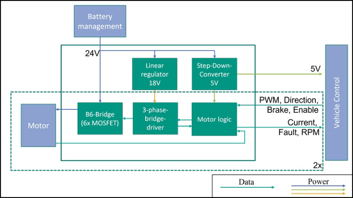
Power Management PCB An overview of the power management PCB is shown in Figure 2. It receives motor control signals from the vehicle control PCB to drive the brushless DC motors used in the system. Additionally, it provides battery voltage and motor speed information to the vehicle control PCB, allowing for more advanced vehicle control and monitoring.
Figure 2: Overview of the power management PCB.
The power management PCB’s main functionalities are controlling the motors through a three-phase bridge configuration and supplying different voltage levels required by the different system components. Receiving sig- nals from the control, the power management PCB generates gate signals for the driver based on the current motor position, which is obtained from the motor’s hall sensors. Moreover, the PCB incorporates battery voltage and current measurement capabilities.
The power management PCB is designed to be compatible with 24V lead- acid batteries and can independently control two motors. The motors used in the system are rated at 250W, and although they have a nominal current of approximately 11A, they experience higher currents during start-up. There- fore, the power management PCB was designed to handle short-term currents of up to 40A, ensuring safe and effective heat dissipation.
The motor logic serves as a connection between the Hall sensors’ feed- back, control specifications, logic signals for the gate driver, and possible error signals. Each motor requires its own logic module.
Fully integrated drivers for all six bridge gates are used. They offer voltage and current monitoring features, allowing for easy integration of overcur- rent protection. The PCB includes protection diodes for gate voltage spikes, addressing previous issues.
Modularized Platform for an Embedded Systems Case Study: Concept and Design 845
In the selection of components for the power management PCB, particular attention was given to the power stage MOSFETs. MOSFETs with a rated voltage of 75V and a rated current of 76A were chosen, as they exceed the requirements and possess suitable switching times for efficient operation. To ensure the required cooling, one heat sink per three-phase bridge configura- tion is used. Each heat sink is designed to dissipate the power losses generated by six MOSFETs.
The power management PCB requires four voltages: 24V for the motors, 15-18V for the gate drivers, 5V for the Hall sensors and EEPROMs, and 1.8V for current monitoring. Due to the low current requirements and the complexity of the power management PCB, linear regulators were initially chosen for the auxiliary voltages. For 5V the change to a step-down converter was made, as it supplies the vehicle control PCB as well. A transistor regu- lator is used to generate the 1.8V supply. The heat sinks for the MOSFETs were designed with extra space, allowing them to be used for the voltage regulators as well. Four wires (two GND, two 24V) are used for battery con- nection to meet the current rating. This approach allows for smaller wire diameters.
The power management PCB has undergone extensive testing to validate its design and functionality. Various tests were conducted, including motor control tests, battery voltage and current measurement tests, and heat dissi- pation tests. The PCB demonstrated motor control, accurate measurement of battery parameters, and efficient heat dissipation, meeting the design objectives and ensuring reliable operation of the brushless DC motor system.
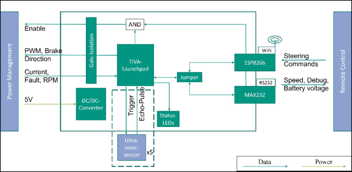
Vehicle Control PCB The vehicle control PCB, as shown in Figure 3, is connected to the power management PCB and the remote control PCB. The connection to the power management PCB is used to supply the vehicle control PCB with power, con- trol the motors, and get information about possible faults, the motor speed, and motor currents. The connection to the remote control enables the user to view the current battery charge and speed while controlling the robot. Five ultrasonic sensors are connected to detect objects in front of the vehicle.
Figure 3: Overview of the vehicle control PCB.
The main function of the vehicle control PCB is to arbitrate the differ- ent inputs and control the vehicle. It acts as an interface between the power management PCB and the remote control PCB, establishing essential con- nections that enable seamless communication and control of the vehicle’s functionalities. Additional functionalities, such as other sensors or higher computing power, could be achieved by replacing this PCB with a different version.
The center of the design is an EK-TM4C123GXL LaunchPad (TIVA LaunchPad) by TI. This enables students to use their own LaunchPad for deploying code to the robot by flashing it before putting it on the robot. A separate benefit of this is reduced design effort.
The LaunchPad receives steering commands by the remote control either via a Wi-Fi connection or (as a backup) an RS232 connection. The used connection can be selected through a jumper, connecting either a MAX232 or ESP8266 to the TIVA LaunchPad. As information for the users, the measured speed, selected debug values, and the battery voltage are sent to the remote control. The messages are sent and received over UART.
As a requirement from a different workshop, all data connections to the power management PCB are galvanically isolated using optoisolators. For the power supply, a DC/DC-Converter with isolation is used. As a safety measure a logic circuit is used to enable the motors only if the TIVA LaunchPad sends an enable signal and the connection to the remote control is stable. The connections for the motor control exist twice, once for each motor.
Another safety measure is the ultrasonic-sensor array. Five sensors are mounted in the front of the vehicle to avoid collisions. This setup is already provided in the original Magni Silver™configuration. To con- trol the sensors a trigger pulse is sent and the width of the echo-pulse is measured.
The vehicle control PCB serves as a crucial intermediary between the power management PCB and the remote control PCB. It facilitates seamless commu- nication, and efficient control of the vehicle’s functionalities, and provides valuable feedback to the user.
Remote Control PCB While the remote control PCB is not mounted on the robot itself, it serves as the front end for the user and receives inputs through four buttons and a joystick. The received inputs are used to navigate a user interface and steer the robot.
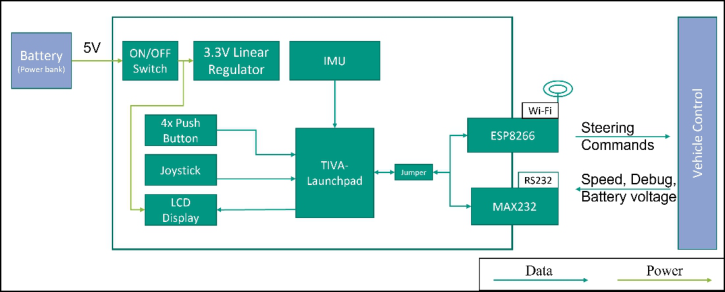
As shown in Figure 4, a battery in the form of a commercially available 5000mAh power bank supplies the system. The remote control PCB can be switched on and off through a lever switch. A linear voltage regulator on the TIVA LaunchPad is used to create a 3.3V level for the peripherals on the PCB.
Modularized Platform for an Embedded Systems Case Study: Concept and Design 847
On the LCD Display information for the user is shown. To switch the displayed information, for example, to a debugging view, four pushbuttons in a cross formation are connected to GPIO-Pins of the TIVA LaunchPad. The joystick contains two potentiometers, one per axis. This allows for an exact control of the steering, by reading the output through the internal ADC of the TIVA LaunchPad. An additional GPIO Pin is connected to the Joystick as it can be pressed as well.
Figure 4: Overview of the remote control PCB.
As a secondary means of control, an inertial measurement unit (IMU) can be mounted to the PCB. The idea is to lean the remote control to steer the robot. This possibility is however not used for the workshop, as it does not seem necessary. The IMU is connected via I2C to the TIVA LaunchPad.
Same as for the vehicle control PCB, two separate possibilities for con- nection are implemented. The primary data exchange is over a Wi-Fi connection through an ESP8266, while an RS232 connecter serves as the backup. The selection of the channel again is made by changing a jumper on the PCB.
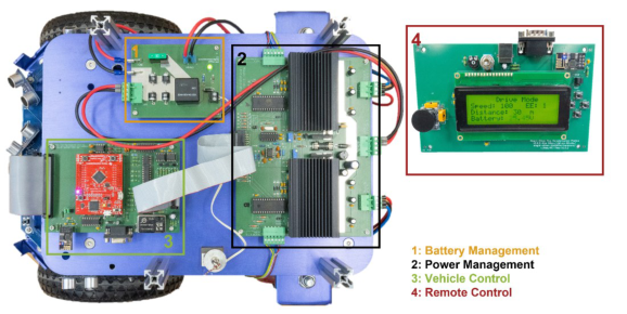
Deployed Hardware Platform To show the hardware platform in its finished version, Figure 5, gives a bird’s eye view of all the PCB. On the upper left is the battery manage- ment PCB (1). The power management is located in the center, identifiable with its heatsinks to facilitate the losses in the MOSFETs and voltage con- verters. The vehicle control PCB (3), with the prominent placement of the TIVA LaunchPad in red, is on the lower left. Finally, the remote control PCB (4) shows the User Interface in the LCD-Display. The TIVA Launch- pad on the remote control is mounted on the backside, and therefore not visible.
Figure 5: The deployed hardware platform.
CONCLUSION
Project-based learning is an important aspect of teaching engineering students in early semesters. It helps to keep them engaged with the study program and teaches important soft skills while cementing the contents from lectures and exercise classes. With the new hardware platform introduced in this paper, students will be able to learn about hardware-oriented programming. The design was chosen to be as modular and maintainable as possible while allow- ing for future expansions, changes, and upgrades. Overall, the hardware platform provides first-year electrical engineering students with a practi- cal and comprehensive introduction to hardware-oriented programming and project management. By integrating software and hardware components, the platform promotes a holistic understanding of systems engineering principles.
REFERENCES
Beuth, Thorsten/Ayhan, Serdal/Zwick, Thomas (2013). Einführung eines fakultätsund semesterübergreifenden, frühphasigen Teampraktikums für die elektro- und informationstechnischen Bachelorstudiengänge am KIT. In: Beuth, Thorsten/Gädeke, Tobias/Tradowsky, Carsten/Becker, Jens/Klimm, Alexan-
der/Sander, Oliver (2015). The Road to “ITIV Labs” – An Integrated Concept for Project-Oriented Systems Engineering Education. International Journal of Infor- mation and Education Technology 5 (4), 250–254. https://doi.org/10.7763/IJIET. 2015.V5.511. Jollands, Margaret/Jolly, Lesley/Molyneaux, Tom (2012). Project-based learning as a contributing factor to graduates’ work readiness. European Journal of Engineering Education 37 (2), 143–154. https://doi.org/10.1080/03043797.2012.665848. O’Kelly, Matthew/Sukhil, Varundev/Abbas, Houssam/Harkins, Jack/Kao, Chris/-
Pant, Yash Vardhan/Mangharam, Rahul/Agarwal, Dipshil/Behl, Madhur/Burgio, Paolo/Bertogna, Marko (2019). F1/10: An Open-Source Autonomous Cyber- Physical Platform. Available online at https://arxiv.org/pdf/1901.08567. Tradowsky, Carsten/Lauber, Andreas/Werner, Stephan/Beuth, Thorsten/Müller- Glaser, Klaus/Sax, Eric (2015). Porter for the ITIV LABS – Objective-Related Engineering Education in an Undergraduate Laboratory. Journal of Teaching and Education (JTE) 4, 45–58. Ueter, Niklas/Chen, Kuan-Hsun/Chen, Jian-Jia (2020). Project-Based CPS Educa-
tion: A Case Study of an Autonomous Driving Student Project. IEEE Design & Test 37 (6), 39–46. https://doi.org/10.1109/MDAT.2020.3012085.
Read this individual research paper free through the original publisher, or explore the full digital proceedings book.
ISBN 978-1-958651-87-2
Explore this ISBN in the AHFE Bookstore ↗Listed in the July 2026 bookstore catalogue; search by ISBN to confirm current availability · Digital book purchase optional