Yuna Haas, Eric Sax (2024). Conceptual approach of an online correction system for the stent production. In: Human Interaction and Emerging Technologies (IHIET 2024). AHFE Open Access, vol. 157, pp. 593–602. https://doi.org/10.54941/ahfe1005519
Stents are the most common form of treatment for coronary heart disease (CHD). Therefore, in Germany, in 2020, 298,557 stents were implanted. Nonetheless, they are relatively expensive. According to the German fee-per-case system, the cost of a single stent can range from 42.17 € up to 1,391.27 €. One possible reason for these costs is the lack of an automated inspection and correction system for maypole braided stents.In this paper, a concept for an online correction system of the stents’ geometry during production is proposed. In contrast to existing proposals, the concept does include the un- and re-braiding of the stent if necessary. This leads to existing errors in the stent being corrected rather than only focussing on the future braiding process. This can on the downside lead to a recursive un-braiding of the complete stent. Therefore, a recursion-prevention is included. Further, multiple options to compute the adapted take-up speed of the Mandel, including a mathematical as well as an AI-based approach, are discussed. Moreover, the concept can handle a complete description of the geometry to be produced, as well as a description based on the mandrels' take-up speed, which is more common for stent producers. All in all, the concept contains three steps. In the first steps, it is detected, if a correction is necessary and the recursion-prevention is applied. In the next step, the number of braid cells, that have to be un-braided, as well as the adapted take-up speed are computed. In the last step, the communication of the changed braiding parameters to the maypole braider, as well as the propagation of the take-up speed regarding the remaining production process, are handled.
In Germany, 985,572 citizens died reportedly in the year 2020 (Radtke, 2023). The leading cause of death are diseases of the circulatory system (36.4 %) (Radtke, 2023). The coronary heart disease (CHD) belongs to this group of diseases and represents, with 121,725 deaths, the most common (single) cause of death (Herzstiftung, 2022). The main cause of CHD is a narrowing of the coronary vessels, which will lead to an insufficient supply of oxygen and nutrients to the heart muscle (Schlüssel et al., 2022). This undersupply can cause heart failure, cardiac arrhythmia or heart attack (Schlüssel et al., 2022). A possible treatment for this narrowing, and therefore the CHD, is the implantation of a stent (Schlüssel et al., 2022). The stent will widen the
narrowing and therefore restore the supply of oxygen and nutrients (Schlüssel et al., 2022). Due to this reason, there were 298,557 stent implantations in Germany (Herzstiftung, 2022). Incorporating that, according to the German fee-per-case system, a single stent costs 42.17 € up to 1,319.27 € (section 17b of the German Hospital Financing Act, in the version for the year 2023), the financial burden on the public sector is evident. A possible reason for these high costs must be the lack of an automated inspection and correction system during stent production with a maypole braider (Bermudez et al., 2017). Currently, the stent is manually inspected for errors after its production (Bermudez et al., 2017). If there is an error in e.g. its geometry, the stent is disposed of (Haas et al., 2022). Therefore, an inspection system, which can detect and correct geometry errors, during production, is desirable.
FUNDAMENTALS Stent Production
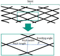
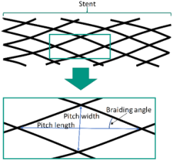
A maypole braider (s. Figure 1), which can be used to produce stents, contains three main components. The first one is the carriers, which move in a pairwise opposite direction and are propelled by horn gears. In addition, they store the braiding wire. The braiding wires’ other end is fixed at the mandrel, which corresponds to the second main component. During braiding, the mandrel moves vertically away from the carriers’ movement plane. Its movement speed is called take-up speed. The last component is the braiding ring. It is being used to control the stents’ geometry. Apart from that, the mentioned take-up speed, the tension, as well as the diameter of the braiding wire, the to-be-braided pattern, and the mandrels’ shape, influence the stents’ final geometry. This geometry can be described as a mesh (s. Figure 2). A single mesh, or braiding cell, can be characterized using its pitch length and width or braiding angle. The pitch length and width are defined as the distance between the top- and bottommost respectively the left- and rightmost interlacing point of the braiding wire of a braiding cell. The braiding angle describes the angle between the braiding wire and the stents’ axis (Kyosev, 2014) Based on this mesh structure, a row and column index can be assigned to each braid cell (Haas, Stang et al., 2021).
Figure 1. Schematic visualization of a maypole braider and its main compo- nents (Haas, Braeuner et al., 2021).Figure 2. Schematic visualization of a stent as a mesh as well as its braiding angle, pitch length and width.
Conceptual Approach of an Online Correction System for the Stent Production 595
RELATED WORK
Currently, there aren’t any systems or conceptual work regarding an inspection and correction system for maypole braided stents. However, there are systems, which measure the braiding angle using e.g. a Fourier transformation (e.g. (Jiyong et al., 2023; Ershov et al., 2022; Yang et al., 2022) or (Vollbrecht et al. 2021)), a Hough Transformation (Monnot et al., 2017) or Convolutions Neural Networks (CNNs) (¸Serban & Barsanescu, 2020) of composite braids. These methods have in common, that the measurement is performed over multiple braid cells. Therefore, an error localization on braid cell level is not possible. In Addition, some of these systems adapt the future braiding process based on braiding angle measurements (e.g. (Jiyong et al., 2023; Yang et al., 2022) or (Vollbrecht et al., 2021)). This adaption does not include a correction of the observed error and lacks a precise error localization.
REQUIREMENTS If an error correction system is implemented, then requirements regarding the maypole braider as well as the measurement system arise. The maypole braider needs to be able to start, stop, and adapt the braiding process at will and in real time. In doing so, the correction process can be started as soon as an error is detected. Moreover, it must be able to braid and un-braid to a specific braid cell at a specified index with or without adapted parameters. This is necessary because the stent has to be un-braided up to a specific braid cell and afterward resume the braiding process using adapted parameters. This requires the braider to know the index of the currently braided braid cell. Otherwise, it cannot un-braid to a specific one. If the maypole braider does not know the current braid cell index, then the error correction system has to compute it. This conversion would require insight into the maypole braiders’ setup and parameterization. Following this, additional computing resources would be necessary. Therefore, to operate more resource-efficient and preserve a decoupled system, the maypole braider needs to be able to operate braid cell indexed. Moreover, the braider needs to offer some kind of programmable interface (API). Otherwise, the correction system cannot communicate with the machine. In this paper, only changes in the mandrels’ take-up speed are addressed. Therefore, the API needs to provide read and write access to the mandrels’ braid cell indexed take-up speed.
Further, the measurement system must be able to measure and locate single- braid cells in real-time, e.g. as proposed in Haas & Sax (2023). The location needs to contain a row and column index (s, t). Otherwise, a comparison with the desired structure is not possible. In Addition, it should be executed independently from the correction system. This is necessary because both systems have to be executed in parallel. Otherwise, it would be impossible to measure during a correction.
Lastly, the expected geometry specifying the braid angle and/or the pitch length and width as well as additional braid-specific parameters, like the mandrels’ diameter, are needed. One possible implementation method would be to extend the braiders API.
596 Haas and Sax
CONCEPT Approach Classification
Before presenting the concept, two characteristics of the proposal must be specified:
1. Expected geometry: Is the expected geometry a description based on single braid cell definitions or is it a time-dependant take-up speed profile? 2. Range: Should the system operate area-based or single braid cell based?
The first point addresses the required description of the expected braids’ geometry. This paper covers two different description methods. The first one is based on a description of each single braid cell. This can be interpreted as some sort of table including the index of each cell and its corresponding size. The second one is the description of the mandrels’ take-up speed as well as the horn gears’ speed. Using these two factors, the expected geometry can be computed (idealized).
The second point discerns if the system corrects every single braid cell (single braid cell based) or if it accepts deviations (area-based). The area- based approach is restricted to accepting deviations only
1. If the braid cell is located in an area of a stent where a geometry change (geometry changing area) occurs, and 2. If the deviation converges to the expected value over a specified number of braid cells.
This can lead to a reduction of correction cycles, accepting deviations from the specification.
In practice, the two characteristics correlate with each other. Meaning, that if the expected geometry is based on single braid cell definitions, then one would assume a single braid cell based correction to happen. Otherwise, the geometry would not match the specification. If the expected geometry is based on the mandrel’s take-up speed, then the implicit braid cell description is idealized and therefore faulty. In this case, the system can, using the area- based approach, accept deviations from this description to avoid unnecessary correction cycles.
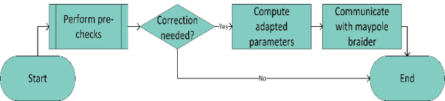
Top-Level Concept The proposed concept contains three major steps (s. Figure 3). In the first step, pre-checks are performed. Then, the parameters to adjust the braiding process are computed. Lastly, the results have to be communicated. Due to the measurement system measuring a single braid cell per measurement, the correction system is based on the correction of a single braid cell as well. The case of measuring multiple braid cells at once isn’t part of this paper.
Conceptual Approach of an Online Correction System for the Stent Production 597
Figure 3: Visualization of the three major steps in the correction process.
Pre-Checks In the scope of the pre-checks, four different aspects will be handled:
1. Does the deviation of the measured from the expected geometry exceed a defined threshold? 2. Is the stent being un-braided? 3. Is a recursive correction happening and allowed? 4. Are the approaches prerequisites fulfilled?
The first step tests, if a deviation occurred, which should be corrected. In specific, the measured braid cell is compared to the expected one. If the deviation is smaller than a certain value (e.g. as the error described in (Haas, Braeuer et al., 2021)), then it is ignored and no correction will be applied.
The second step is to verify if an un-braiding is happening. Because of the inversed movement speed of the mandrel during the un-braiding, all inspected braid cells have been inspected before. Therefore, there shouldn’t be any corrections necessary.
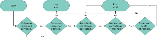
The third step handles recursions (s. Figure 4). At first, it is checked if a braid cell with a higher row index exists, which was previously corrected and if recursions are allowed (by the user). If both questions are answered with yes, then it is checked, whether the same braid cell was previously corrected. If so, the number of previous corrections is compared to a threshold value. The same procedure will be repeated for the depth of recursion. This will prevent an infinite correction loop of a single braid cell as well as the whole stent.
Figure 4: Recursion prevention procedure.
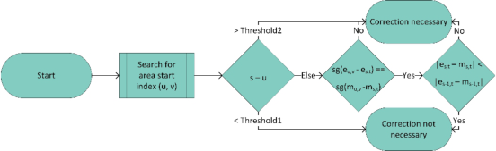
In the last step, it is analyzed, whether the approaches’ prerequisites are fulfilled. In the single braid cell case, this step can be skipped, because the deviation of a single braid cell suffices to trigger a correction. The area-based one contains the following steps (s. Figure 5):
598 Haas and Sax
1. Search for the row and column index of the braid cell (u, v) at the start of the geometry changing area. This braid cell will be used as a reference. 2. Compute the difference between the row index of the currently braided cell s and u. Then, compare the value: a. If s – u < Threshold1, then a correction is not necessary. b. If s – u > Threshold2, then a correction is necessary. c. Otherwise continue with the procedure.
Using Threshold1 and Treshold2, a minimal and maximal size of the geometry changing area can be defined.
3. Check if the sign of the difference of the expected geometry at (u, v) and (s, t) is the same as the measured one at (u, v) and (s, t). If it isn’t, then a correction is necessary. This ensures that the change in geometry has the same sign. This means that if e.g. the expected geometry increases, the measured one should as well. 4. Compute the absolute difference between the expected and measured geometry at (s, t) and (s-1, t). If the value at (s, t) is smaller than the one at (s-1, t), then a correction is not necessary. Otherwise, the error increases, and a correction is necessary. If Threshold1 is smaller than one or not being used, then this step should be skipped if s is equal to u.
If a correction is necessary, the correction system uses the maypole braiders’ API to stop the braiding process.
Figure 5: Prerequisites check of the area-based approach with ea,b and mc,d being the expected and measured braid cell at index (a,b) and (c,d).
Compute Adapted Parameters In the next step, the number of un-braided braid cells as well as the take-up speed adjustment(s) are computed. The procedure changes depending on the chosen approach (single braid cell vs. area-based). The cause for this is, that in the single braid cell case, all braid cells are assumed to be correct up to the incorrect one. Therefore, the un-braiding will always be performed up to the incorrect one. In the area-based case, the un-braiding can be performed up to any braid cell in the geometry changing area.
Single Braid Cell Approach To compute the take-up speed adaption using the single braid cell approach, multiple procedures are possible. In this paper, three possibilities are
Conceptual Approach of an Online Correction System for the Stent Production 599 explained briefly. The first one is mathematical1. It uses the deviation between the expected and measured geometry. In the case of the pitch length being the measurement criteria, the new take-up speed vnew can be computed as shown in Equation 1. In this equation vold, ae, am and rpm describe the previously used take-up speed, the expected and measured pitch length as well as the horn gears RPM.
vnew = vold + (ae −am) ∗rpm (1) The second one is a regression based on deep learning (DL). In specific, a deep neural network will be used to compute the deviation directly. The input to the networks needs to cover important information like the deviation of the measured to the expected geometry or the mandrels’ diameter. The last one is (deep) reinforcement learning (RL). The (RL) states correspond with the expected and measured geometry, machine parameters like the current take-up speed, and other relevant parameters like the mandrels’ diameter. The (RL) action is defined as an adaption of the take-up speed. Lastly, the reward corresponds to the deviation between the expected and the measured geometry.
Area-Based The area-based approach consists of two steps: First compute the number of braid cells being un-braided and second, compute the take-up speed adaption, except for (deep) RL, which will compute both parameters at once.
Two possibilities to compute the number of un-braided braid cells are:
1. Rule-based: Always un-braid to the start of the geometry change area. This is valid because deviations are allowed, as long as the deviation is lower than a specified threshold. 2. Deep Learning: Using a DL-based regressor, the value can be computed using braid-relevant information like the expected and measured braid cell and the mandrels’ diameter.
Afterward, one of the methods described in the previous chapter (Single braid cell approach) can be used. In the second case (DL-based regressor), the regressors’ input will be extended such that the number of un-braided braid cells will be used as well.
Alternatively, RL can be used to compute both parameters at once. In this case, the (RL) state corresponds to the expected and measured geometry and relevant machine parameters like the mandrels’ diameter. An (RL) action will be to compute the number of un-braided braid cells as well as the adapted mandrels’ take-up speed profile for these braid cells. The (RL) reward will be defined as the negative absolute difference between the expected and measured geometry at the correction triggering braid cell.
1Due to the scope of this paper, the mathematical approach is held rather simple. More (mathematical) complex approaches can be found in e.g. (Jiyong et al., 2023).
600 Haas and Sax
Communicate With Maypole Braider In the last step, the communication with the maypole braider is handled. This communication can be divided into four steps: 1. Offset-computation, 2. Communicate adjustments, 3. Reset internal states and 4. Resume braiding. In the first step, an offset has to be added to the number of un- braided braid cells. The reason for this is, that the measurement system detects finished braided cells. Therefore, there is a discrepancy between the currently braided and detected braid cells. This discrepancy can be computed by comparing both indices. The first one can be retrieved using the braiders API, while the second one is a result of the measurement system. The difference between those two values corresponds to the mentioned offset. In the second step, the adjusted take-up speed profile has to be communicated to the maypole braider using its API. In the third step, internal states have to be reset. E.g. if a braid cell is un-braided, then all previous measurements of its geometry are invalid. In the last step, the braiding has to be resumed.
DISCUSSION
Revisiting the requirements, it is assumed, that the maypole braider can operate indexed based. This can, in a practical implementation, be problematic. Due to the restrictions of the embedded system controlling the braider, it is possible, that there aren’t enough computing resources to realize this functionality. Therefore, the decision, whether or not the braider can be controlled using an index, is dependent on its as well as the controlling systems computing and network resources. If the correction system could compute the index, then the localization system would not be necessary. This would require, that the measurement system is not noised. Otherwise, the mapping of the measurement to its index would be biased, even if both computations are correct in themselves.
Another requirement is that the measuring system must be able to measure the row and column index. This is necessary for correct localization. Conventional systems often do not provide control over single carriers. Therefore, all braid cells of one row are identical. In this case, a column-wise localization is not necessary and can therefore be discarded.
Further, the two possibilities single braid cell and area-based were introduced. The first one assumes to be a correct description on braid cell level. The second one is interpreted as a faulty description, especially if changes in the braid pattern occur. Following this, one could mistake them for two opposing procedures. In reality, they represent two different use cases. In the first one, a final description of the stent to be produced is available. The second one is based on the braiders’ take-up speed profile and therefore cannot represent the stents’ geometry correctly.
Regarding the approach prerequisites, there are two thresholds to be set. Both values can be set to trivial values like 1 (Threshold1) and infinity (Threshold2). However, this would make them incapable of controlling the geometry changing areas’ size. To choose useful values, insight into the stent being produced is necessary. Due to the reason, that this check is only applicable to the area-based approach, which, per definition, lacks this
Conceptual Approach of an Online Correction System for the Stent Production 601
knowledge, it is likely, that trivial values will be chosen making the checks obsolete.
Furthermore, the correction system is not generally applicable. The area- based approach requires the stent to reach the expected value before another change is applied. Otherwise, the approach prerequisites computations are faulty. In Addition, in this case, it is not ensured, that the expected value of the initial geometry change is reached.
SUMMARY AND OUTLOOK In summary, a concept is proposed, which corrects a stent’s geometry in case of an error during its production using a maypole braider. This concept contains three major steps: At first, pre-checks are performed. This includes e.g. a check if a correction is necessary as well as a (infinite) recursion prevention. If a correction is necessary, then the adapted parameters are computed in the second step. This includes the number of braid cells being un- braided as well as the take-up speed adaption after the un-braiding. For both parameters, different methods (mathematical, DL, and RL) are presented. In the last step, the parameters are communicated to the braider.
Regarding future work, the described methods, which compute the specified parameters, could be implemented and evaluated. In Addition, the proposed system could be extended to support the detection of multiple braid cells at once. This can be realized in two different ways. The first one would be to run this proposal in parallel. In this case, a harmonization of all correction values is needed if an error occurs. Alternatively, the procedure could be changed such that multiple braid cells are processed at once. This could be advantageous because the single braid cells can be set in context.
ACKNOWLEDGMENT
Parts of this work have been developed in the project Stents4Tomorrow. Stents4Tomorrow (reference number: 02P18C022) is partly funded by the German Federal Ministry of Education and Research (BMBF) within the research program ProMed.
REFERENCES
Bermudez, C., Laguarta, F., Cadevall, C., Matilla, A., Ibañez, S., & Artigas, R.
(2017). Automated stent defect detection and classification with a high numerical aperture optical system. In Automated Visual Inspection and Machine Vision II (p. 103340C). Deutsche Herzstiftung. (2022). Mortalitätsrate aufgrund von Herzkrankheiten in Deutschland nach Diagnosegruppen in den Jahren von 1990 bis 2020 (je 100.000 Einwohner). Ershov, S. V., Reimer, V., Zastrow, T., Kalinin, E. N., & Gries, T. (2022). Method for
measuring the braid angle and its deviation from the specified value in braided preforms using image analysis. Fibre Chemistry, 53(5), 346–354. Haas, B., Braeuner, M., Lehmann, K., & Sax, E. (2021, October). Evaluation of different methods to measure a stent’s pitch length in an industrial environment.
602 Haas and Sax
In 2021 International Conference on Electrical, Computer, Communications and Mechatronics Engineering (ICECCME) (pp. 1–6). IEEE. Haas, B., Erlinghagen, L., & Sax, E. (2022, November). Pitch length measurement of stents using dynamically cropped images. In 2022 International Conference on Electrical, Computer, Communications and Mechatronics Engineering (ICECCME) (pp. 1–6). IEEE. Haas, B., & Sax, E. (2023). Conceptual measurement of individual pitches during
the stent production. Proceedings of 17th International Conference on Computer Graphics, Visualization, Computer Vision and Image Processing, 115–122. Haas, B., Stang, M., Khan-Blouki, V., & Sax, E. (2021). Introduction of an Algorithm Based on Convolutional Neural Networks for an Automated Online Correction of Braided Cardiovascular Implants. In Human Interaction, Emerging Technologies and Future Applications IV: Proceedings of the 4th International Conference on Human Interaction and Emerging Technologies: Future Applications (IHIET– AI 2021), April 28-30, 2021, Strasbourg, France 4 (pp. 28–36). Springer International Publishing. Hoffstetter, M., Pfeifer, S., Schratzenstaller, T., & Wintermantel, E. (2009). Stenting
und technische Stentumgebung. Medizintechnik: Life Science Engineering, 1263–1296. Jiyong, F., Yujing, Z., Zhongwei, W., & Zhiguo, Y. (2023). Traction control of space tubular shaped mandrel and detection of preform braiding angle. Textile Research Journal, 93(1-2), 392–408. Kyosev, Y. (2014). Braiding technology for textiles: Principles, design and processes.
Elsevier. Monnot, P., Lévesque, J., & Lebel, L. L. (2017). Automated braiding of a complex aircraft fuselage frame using a non-circular braiding model. Composites Part A: Applied Science and Manufacturing, 102, 48–63. Rainer Radtke. (2023). Anzahl der Todesfälle nach den häufigsten Todesursachen in
Deutschland in den Jahren 2019 bis 2021. Schüssel, K., Weirauch, H., Schlotmann, A., Brückner, G., & Schröder, H.
(2022). Gesundheitsatlas Deutschland. Koronare Herzkrankheit: Verbreitung in der Bevölkerung Deutschlands: Ursachen, Folgen und Präventionsmöglichkeiten [White paper]. Wissenschaftliches Institut der AOK (WldO). ¸Serban, A., & Barsanescu, P. D. (2020, December). Automatic detection of fibers orientation on composite laminates using convolutional neural networks. In IOP Conference Series: Materials Science and Engineering (Vol. 997, No. 1, p. 012107). IOP Publishing. Vollbrecht, B., Kohler, C., Kolloch, M., Jung, F., Grigat, N., & Gries, T.
(2021). Developing a camera-based measuring system to feedback control the fibre orientation for the braiding process of CFRP. Advances in Industrial and Manufacturing Engineering, 3, 100059. Yang, M., Yu, L., Wong, C., Mineo, C., Yang, E., Bomphray, I., & Huang, R.
(2022). A cooperative mobile robot and manipulator system (Co-MRMS) for transport and lay-up of fibre plies in modern composite material manufacture. The International Journal of Advanced Manufacturing Technology, 1–17.
LISTED IN THE AHFE DIGITAL BOOKSTORE CATALOGUE
Explore the complete digital volume
Human Interaction and Emerging Technologies (IHIET 2024)
Read this individual research paper free through the original publisher, or explore the full digital proceedings book.
ISBN 978-1-964867-33-5
Explore this ISBN in the AHFE Bookstore ↗Listed in the July 2026 bookstore catalogue; search by ISBN to confirm current availability · Digital book purchase optional