Alexander Letzel, Daniel Schilberg (2023). Adapting a 3D Printer as a Robot for Testing Electronic Control Units in Automotive Context. In: Emerging Technologies and Future of Work. AHFE Open Access, vol. 117, pp. 66–75. https://doi.org/10.54941/ahfe1004406
As a result of a multitude of safety- and comfort-functions, most modern automobiles contain various electronic control units. The automobiles’ passengers can control several of those functions not only by activating mechanical switches, but also by using sensory control elements. Sensory control elements mostly use capacitive effects induced by contact to determine whether a function should be executed. Aforementioned contacts might be in the form of touches or slides. During the development of sensory control elements, it is desirable to test the devices as early and as often as possible to ensure a continual adaption of sensor calibration and evaluation. The significance of such tests is provided by repeating tests at equal positions with comparable velocities and applied forces. Therefore, robots are already used to perform such tests. The operational availability of the previously mentioned robots has been proven to be too short, which is why not all developers are provided with sufficient test capacities. To approach this problem, the development of a duplicatable robot system with respect to a constrained budget has been realized. Due to the high costs of complete robot systems, this thesis contains an experimental approach by remodeling a 3D printer. An adequate system has been developed by remodeling mechanical-, hardware- and firmware aspects of the original system. Furthermore, a user software has been programmed. Essential aspects of the remodeling include construction designs for mechanical changes, hardware- and firmware integration of a force sensor, implementing a force-dependent stop of movements and communication with the user software. Essential aspects for the user software include the design of a GUI as an interface between the user and the system, the automatic generation of coordinated movements and communications with the robot. Further development should include an improved validation of force measurements, a more accurate force-dependent stop, more accurate determination of reference points and the optimization of the built-in working area. Additionally, the current force sensor only measures forces in one axis. It is suggested to replace it with a three-axis sensor.
Contemporary automobiles contain a multitude of Electronic Control Units (ECUs) (Brünglinghaus, 2014), (Syrma SGS, 2020). ECUs receive sensory inputs which are evaluated and processed by a built-in processor. An ECU also controls actuators to execute functions. Additionally, all ECUs in a
Adapting a 3D Printer as a Robot for Testing Electronic Control Units 67
vehicle are connected to a Binary Unit System (BUS) for communications. Typically used BUS-systems in automotive are Controller Area Network (CAN), Local Interconnect Network (LIN) or FlexRay (Zimmermann and Schmidgall, 2014). A modern approach for passengers to execute functions from within a vehicle uses ECU sensory control elements. A roof module for e.g., contains two highlighted sliders accessing the sunroof settings of a vehicle and additional sensory control elements to manage passenger lights, service-requests, etc. The sensory control elements’ surface gives access to all functions which can be performed by the ECU. Typically, functions are executed by passengers by either touching the surface of the sensory ele- ments or performing a slide-movement. To react correspondingly to the passengers’ input, firmware and hardware of ECUs must derive when, where and for how long a touch or a slide has been performed. To obtain this information, raw sensory data must be processed e.g., by filtering and comparing filtered data to a baseline. The process of developing a reliable baseline is difficult and underlies a variety of uncertainties while in devel- opment, such as the type of sensors used and whether the sensor type is changed during development process. Therefore, a multitude of tests are performed in each ECUs development process. Each tests requires several hundred iterations throughout the development process. To deduce meaning- ful conclusions from test iterations it is necessary to repeat these tests with comparable test parameters, such as the test finger’s position, applied force, etc. Therefore, the usage of industrial robots is desirable. Currently estab- lished robot systems have been proven to perform well at such tasks, but the availability is too low to provide every developer with sufficient time for testing. This circumstance impairs the development processes’ efficiency by either stalling developers until accessing a robot system or continuing development without testing, leading to an increased number of errors. Extending testing capabilities by providing more of the established robot systems is economically unviable, as the investment of one system sums up to ∼80000€ (KOSTAL, 2022). Therefore, this paper researches the possi- bility of developing a duplicatable test system with respect to a constrained budget.
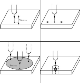
Current State of Testing Environment for ECUS With Sensory Touch Control ECUs are predominantly tested in a Hardware-in-a-loop (HiL)-environment. HiL-environments simulate an ECUs real working environment without the necessity of implementing the ECU into a real car. This results in meaningful test data while at the same time reduces test efforts (Borgeest, 2021). The HiL- environment includes the sensor simulation of the ECU. One way to establish sensor simulation of sensory control elements is to use robots equipped with test fingers. It shows the movement of a testing finger with respect to the surface of a sensory control element surface. The top-left shows a simple approach to the module from a defined height h, the top-right shows a slide- movement on the element’s surface, the bottom-left describes a landmark-test
68 Letzel and Schilberg
which can be understood as an 2D-array of the top-left test. The bottom- right test comprises the measurement of an in-built force-sensor of the tested element.
Ambitions and Requirements of the Testing System The focus of this papers’ development process was to develop a test sys- tem for ECUs with sensory control elements. The test system does not replace the more sophisticated test systems mentioned in chapter I. Instead, it will be used for early stages in ECU development to provide a repro- ducible test system to thwart testing shortages. All final acceptance tests will still be performed by the more sophisticated testing systems. Nonethe- less, the new test system had to fulfil requirements for its use as seen in Table 1. It is mandatory for the new system to perform all tests the ECUs currently undergo. Developers shall not need in-depth knowledge about the system to be able to use it. Both, the movement velocity, and the repeatability are usual requirements in terms of ECU testing in auto- motive industry (KOSTAL, 2022). It is important to notice, that both requirements need to be fulfilled simultaneously. Both requirements of the mechanical fastening result from a reusability of already prevalent test fingers and mountings for ECU tests. The size of the work area repre- sents the largest ECUs under test. The overall budget has been targeted at 2000€ because of company-internal budgeting. In addition to these require- ments, the new testing system underlies further constraints. Looking at ECU surfaces, it becomes evident that the testing system must perform movements in three dimensions to reach each sensory control element without having to reposition an ECU several times (KOSTAL2, 2022), (KOSTAL 3, 2023). In addition, touches must be performed with defined forces, firstly to prevent destruction of elements and secondly to provide repeatable tests. Therefore, a force sensor needs to be included. Furthermore, a software GUI (graphical-user-interface) is necessary to provide simple usage for developers.
Figure 1: Four typical tests for testing sensory control element surfaces. Top-left: approach-test, top right, slide-test, bottom-left: landmark-test, bottom-right: approach- test with in-built-force-sensor.
Adapting a 3D Printer as a Robot for Testing Electronic Control Units 69
Table 1. Test system requirements.
Table available in the original PDF paper.
Characteristic Requirement Types of tests See Fig. 1 Developer training time for usage <8h Movement velocity ≥150 mm/s Repeatability ≤0,5mm Mechanical fastening of the base plate 25mm x 25mm grid pattern, M6 thread Mechanical fastening of the test finger M5 thread Size of work area (bxlxh) ≥300mm x 300mm x 150mm Cost for a single system ≤2000€
Choice of a Basic System While researching for robotic systems, it became evident that budget con- straints (Table 1) are immediately exceeded with the approach of buying robot systems including user software (Kuka, 2022), (igus, 2022), (Fanuc, 2022). Therefore, an experimental approach has been chosen by expand- ing research from considering only industry robots to considering similar systems such as non-industry robots, 3D-printers, and CNC (computerized- numerical-control)-machines. A list of potential basic systems could be created, (FLSUN, 2022), (STEPCRAFT, 2022), (VARIOBOTIC, 2022). None of the systems could fulfill all requirements presented in chapter IV, though. The 3D-printer constructed by FLSUN shown in Fig. 6 has been chosen because it fulfills the test system requirements regarding movement velocity, repeatability, three-dimensional movements, size of work area and budgeting (FLSUN, 2022). Further advantages are its open-source-firmware (Marlin, 2022) and open-source-hardware (MKS-Robin-Nano, 2022), which facilitate the planning for firmware and hardware adjustments.
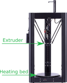
Analysis of Necessary Changes The fulfillment of all test system requirements (Table 1) required mechanical-, hardware-, firmware and software adjustments. Mechanical adjustments shall provide the possibility for reusing test fingers and mountings for ECUs. Therefore, it was planned to replace the heating bed (Fig. 2) of the basic test system with a fitting baseplate for ECU mountings. Additionally, the extruder (Fig. 2) will be replaced with an adapter plate as an attachment point for test fingers. Hardware adjustments consisted of integrating a force sen- sor and a measurement amplifier for touch force regulation. Implementing a measurement amplifier into the design is necessary to amplify low voltages from the force sensor and reduce the influences of electrical interferences and random noise (HBM, 2022), (Winfried Gehrke et al., 2016), (Hongzhi, 2022), (Kitchin and Counts, 2006). The open-source hardware schematics (MKS-Robin-Nano, 2022) have been used for planning.
70 Letzel and Schilberg
Figure 2: FLSUN SR as basic testing system. Based on FLSUN (2022).
Firmware adjustments included force calculation by reading force sensor data, force-dependent stopping for reliable repeatability while testing and as a safety-measure against applied forces which could destroy ECUs. Fur- thermore, the firmware needs to be able to receive movement commands. In addition to that, force- and positional data shall be communicated by the testing system for later analysis.The controls of the testing system shall be executed by a PC software which makes testing functionalities accessible to developers by way of a GUI. Testing functionalities comprise configuring movements according to the planned test and receiving force- and positional data from the testing system. Calculations proves that the temperature- ISRs’ sensor measurements are too slow for the planned force-measurements. Therefore, the microcontrollers’ direct-memory-access (DMA)-capabilities shall be used.
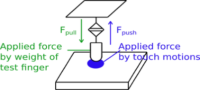
Realization of Planned Changes Mechanical changes have been realized by manual measurements for mechan- ical dimensions and construction in CATIA (3DS, 2023). Hardware adjust- ments were planned in KiCad (kiCad, 2023) and executed by soldering and creating plug-in connectors. Firmware modifications have been performed in C++ and software-programming used python with the GUI-framework Qt (Qt Group, 2023). The base plate fits in as a replacement for the heat- ing bed. Also, it allows for all ECU mountings to be reused by providing a 25x25mm of an M6 thread grid. After removing the extruder, the adapter plate serves as a connection between the test system (Ø3.4mm holes) and applicable test fingers (M5 thread). As to hardware changes, the original hardware will be modified. The integration has been planned according to the block diagram in Fig. 3. Typical force sensors require connections for voltage supply and for its measurement output. The amplifier also requires a voltage supply and provides connections for the force sensors’ measurement output. The output of the amplifier itself shall be read by an analog-digital- converter (ADC) of the systems’ microcontroller for use in its firmware. The force sensor will be connected to a test finger according to Fig. 4. The choice of force sensor and measurement amplifier is based on Table 2.
Adapting a 3D Printer as a Robot for Testing Electronic Control Units 71
Figure 3: Block diagram for force sensor integration.Figure 4: Concept of force sensor and test finger application.Table 2. Force sensor and amplifier requirements.
Table available in the original PDF paper.
Characteristic Value Nominal force (Fn) 20N ≤Fn ≤100N Force direction Push and pull Vsupply for force sensor and amplifier 3.3V, 5V or 24V Vout of amplifier 0V −3.3V Weight of force sensor ≤200g Height of force sensor ≤100g
Therefore, the maximum nominal force has been defined as 100N to con- strain such systematic deviations. Moreover, pushing- and pulling forces need to be applied to the sensor. The pushing forces result from pushing the sen- sory surfaces, the pulling forces result from the test fingers applied to the force sensor. Furthermore, the voltage supplies of force sensor and ampli- fier should be taken directly from available hardware without further need for additional voltage conversion circuits. The amplified voltage needs to be constrained to a range from 0V – 3.3V to use the full range of the micro- controllers’ ADC-input range without risking damaging this input (STM, 2022). The extruder systems (Fig. 2) weight comprises to ∼300g. To pre- vent overstressing the attachment system, the force sensors weight has been limited to 200g to leave a sufficient buffer for the attachment of a test fin- ger (Fig. 4). The maximum height of the force sensor of 100mm has been determined by taking into consideration the maximum printing size of the test system (Fig. 2) of 330mm (FLSUN, 2022), the maximum height of sen- sory control elements of 150mm and typical test finger sizes of 50mm. This leaves a movement buffer of 30mm while tests are performed. The require- ments could be fulfilled by a combination of force sensor and amplifier. But
72 Letzel and Schilberg
Calculations proves that the temperature-ISRs’ sensor measurements are too slow for the planned force-measurements. Therefore, the microcontrollers’ direct-memory-access (DMA)-capabilities shall be used. DMA enables the microcontrollers’ peripherals (e.g., ADCs, communication interfaces, …) to interact with memory directly, specifically without the necessity for the micro- controller to interact with the data (STM, 2022), (Wüst, 2011), (Ahmed et al., 2022). With frequencies available up to several MHz, it also has the capa- bilities to run sufficiently fast for the planned sensor measurements (STM, 2022). For the present real-time task for preventing too high forces, filtering in time-domain will be implemented to minimize time delays for calcula- tions. After implementing the force calculations, communications have been implemented. The firmware will send force-, position- and time-data each millisecond. The implemented data frame is shown in Fig. 5.
Figure 5: Data frame of communication from firmware to PC software.
Figure available in the original PDF paper.
As the last part for implementations, a PC software has been developed. It allows users to define test parameters and supply the robot with instructions to perform tests.
SYSTEM VALIDATION The system validation contains measurement data which shall verify or fal- sify all implementations with respect to the requirements (Table 1). Firstly, the systems’ repeatability of 0,5mm shall be validated. An optical measure- ment has been used. The robot moved to a defined position P with a defined velocity of 150mm/s until the defined force 0.8N has been applied. The ini- tial position A differed for each of the four movements. The tip of the finger consisted of a fine needle which left marks in millimetre-paper. The test results were evaluated with a microscope. Because of the limited reference of 1mm, an exact repeatability value could not be determined. Neverthe- less, it could be shown that the test system accomplishes a repeatability of <0.5mm. The assumed necessary reaction time of 3.27ms is lower than the calculated reaction time of 3.72ms and has therefore been a sufficient assumption.
In the following, the hardware-domain of the force-measurement underlies validation. For the approach-test, a force-path-diagram has been recorded. It was possible to compare the test systems’ force-path-diagram with a recorded measurement of the test system already in use. The same ECU could be tested at two points on its surface. The measurements have taken place five times for each point, before being averaged. The comparisons’ results are shown in Table 11. Table 3 shows that both measurements devi- ate by ∼40%. The number of samples is too low for a well-founded conclusion, although both tests imply a deviation which needs further investigation.
Adapting a 3D Printer as a Robot for Testing Electronic Control Units 73
Table 3. Deviations between two test systems. Tested with one ECU at two points on its surface-area.
Table available in the original PDF paper.
Test system already in use (N/mm)
New test system (N/mm)
Abs. Deviation (N/mm)
Rel. deviation (%)
Point no. 1
33.41 20.45 12.96 38.8
Point no. 2
19.96 12.08 7.88 39.5
In addition to the approach-test, landmark-test can be performed and can also be synchronized to further ECU-data. The process of synchronization will not be discussed here. After each iteration, the x-position shows a move- ment. So, each test point is tested iteratively. Additionally, it is possible to determine the ECU sensor activation. The ECU outputs sensory activation in a binary manner. A zero determines a sensory surface is not activated, a one determines an activation. Therefore, the test system can help to evaluate the sensory control elements activation area. It also becomes evident that the implemented force protection shows overshoots. Where the force applica- tion should stop at -1N, the applied force reaches maxima of -3N. With low velocities, the force shows no overshoot but with high velocities, overshoot- ing occurs. The cause could not be determined, but a hypothesis is presented in the conclusions.
CONCLUSION
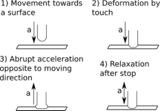
Considering the requirements specified in Table 1, all requirements could be solved. The selected 3D-printer could fulfil the requirements of velocity, size of work area and repeatability and offered room for adjustments for the required mechanical fastenings. The test system can perform all required tests. The accessibility of the test system via the programmed PC-software has been reported as good, although no evidence has been recorded about this topic. With a total amount of 1150€ (without work hours), the budget has been kept. However, the developed test system depicts a prototype, which is recom- mended to receive further adjustment. Firstly, it is recommended to exchange the selected force sensor with a three-axis force-sensor because in case of involuntary mechanical stress in x- or y-direction, the sensor can be destroyed (WIKA). Moreover, the force measurement should be validated with more than the one method which has been presented in this paper. At last, the force protection must be diagnosed for errors which lead to force overshoots at velocities of 150mm/s. A hypothesis for this error is shown in Fig. 6.
Figure 6: Hypothesis for overshooting of force at high velocities.
74 Letzel and Schilberg
The tip of the test finger is made from relatively compressible material. When the tip of the test finger approaches the ECU surface (1), upon touch- ing the surface (2), a deformation occurs. Now, when the force detection steps in (3), the test finger stops immediately, which means it underlies a sudden strong deceleration in the opposite of the moving direction. This results in a back bounce of the finger material. Thus, it applies an additional pushing force. After this, the finger material relaxes (4) so that the pushing force is reduced again. In addition the force deviates while performing the slide. This most likely results from inaccuracies which are transferred from the previ- ously executed interpolation phase. For more accurate force application while sliding, a force regulation may be implemented. Altogether, the experiment of adjusting a 3D-printer to an ECU-testing-system was successful. Developers can use this system to receive results about the ECU in development process without solely having to rely on the more sophisticated testing system, whose availability can now be focused on final acceptance tests.
ACKNOWLEDGMENT
The authors would like to acknowledge KOSTAL Automobil Elektrik.
REFERENCES
Charles Kitchin and Lew Counts. A DESIGNER’S GUIDE TO INSTRUMEN- TATION AMPLIFIERS. 2006. URL: https://www.analog.com/media/en/traini ng-seminars/design-handbooks/designers-guide-instrument-amps-complete.pdf accessed 15 March 2022. Christiane Brünglinghaus, “Elektronik und Software beherrschen Innovationen im
Auto”, May 2014. URL: https://www.springerprofessional.de/automobilelektro nik--software/antriebsstrang/elektronik-und-software-beherrschen-innovatione n-im-auto/6561802 accessed 11 July 2022. 3DS. CATIA. URL: https://www.3ds.com/de/produkte-und-services/catia/ accessed 15 January 2023. Fanuc. M-3 iA/12H. URL: https://www.fanuc.eu/de/de/roboter/roboterfilter-seite/d elta-robots/m3-serie/m-3ia-12h accessed 11 February 2022. FLSUN. Super Racer. URL: https://flsun3d.com/products/super-racer-sr accessed 03
March 2022. HBM. Die Terminologie der Kraftmesstechnik auf einen Blick. URL: https://www.hb m.com/de/3636/glossar-kraftmesstechnik/ accessed 21 February 2022 igus. Drylin Portalroboter. URL: https://www.igus.de/info/portalroboter accessed 09
February 2022. Kai Borgeest. Elektronik in der Fahrzeugtechnik. 2021. ISBN: 978-3-658-02418-5. KiCad. KiCad EDA. URL: https://www.kicad.org/ accessed 15 January 2023. Klaus Wüst. Mikroprozessortechnik. 2011. ISBN: 978-3-8348-0906-3. KOSTAL 2, Dachmodule. URL: https://www.kostal-automobil-elektrik.com/de-de/ empathy/comfort-controls/ accessed 11 July 2022. KOSTAL 3, LKA-Section. URL: https://www.kostal-automobil-elektrik.com/-/medi
a/images/content/automobil-elektrik/empathy/comfort-controls/04-lka-section- bedienelemente.png?as=1&w=1140&hash=47C791733D07BE0D35D7E0DBD D0000AC accessed 7 January 2023. KOSTAL. Dialogue with KOSTAL representatives 04 January 2022.
Adapting a 3D Printer as a Robot for Testing Electronic Control Units 75
Kuka. KR 602-JET. URL: https://www.kuka.com/-/media/kuka-downloads/im ported/6b77eecacfe542d3b736af377562ecaa/db_kr_602_jet_141120_de.pdf accessed 09 February 2022. Li Hongzhi. A BIST (Built-In Self-Test) strategy for mixed-signal integrated circuits”.
2004. URL: https://www.researchgate.net/publication/36146235_A_BIST_Built -In_Self-Test_strategy_for_mixed-signal_integrated_circuits accessed 20 March 2022. Mahammed Altaf Ahmed et al. Design and Implementation of a Direct Memory Access Controller for Embedded Applications. URL: https://ijtech.eng.ui.ac.id/ar ticle/view/795 accessed 25 March 2022. Marlin. Marlin Firmware. URL: https://marlinfw.org/ accessed 13 March 2022. MKS-Robin-Nano. MKS-Robin-Nano-V3. X. URL: https://github.com/makerbase
-mks/MKS-Robin-Nano-V3.~X accessed 13 March 2022. Qt Group. Qt. URL: https://www.qt.io/ accessed 15 January 2023. STEPCRAFT. STEPCRAFT-2/D.420. URL: https://shop.stepcraft-systems.com/STE PCRAFT-D420-Bausatz accessed 03 March 2022. STM. Reference manual. https://www.st.com/en/microcontrollers-microprocessors/s
tm32f407-417/documentation.html accessed 11 March 2022. STM. STM32F405xx STM32F407xx. URL: https://www.st.com/resource/en/datas heet/dm00037051.pdf accessed on 11 March 2022. Syrma SGS, “Automotive ECU: Core Component for Connected Cars”, Septem-
ber 2020. URL: https://www.syrma.com/ecu/#:~:text=The%20standard%20aut omobiles%20running%20on,as%20many%20as%20150%20ECUs accessed 11 July 2022. VARIOBOTIC. DOBOT Magician. URL: https://variobotic.de/robotik-in-schulen/d obot-magician/dobot-magician-technische-daten/ accessed 03 March 2022. Werner Zimmermann und Ralf Schmidgall. Bussysteme in der Fahrzeugtechnik.
2014. ISBN: 978-3-658-02418-5. WIKA. F2812. URL: https://shop.wika.com/de-de/f2812.~WIKA?gclid=Cj0KCQiA ofieBhDXARIsAHTTldqj3LAfSiMFXFsqHjqPF8G-GLf9Plg5gX9QVmUfPD3b bMS5LRJicAMaAki8EALw_wcB accessed on 13 March 2022. Winfried Gehrke at al. Digitaltechnik. 2016. ISBN: 978-3-662-49730-2.
LISTED IN THE AHFE DIGITAL BOOKSTORE CATALOGUE
Explore the complete digital volume
Emerging Technologies and Future of Work
Read this individual research paper free through the original publisher, or explore the full digital proceedings book.
ISBN 978-1-958651-93-3
Explore this ISBN in the AHFE Bookstore ↗Listed in the July 2026 bookstore catalogue; search by ISBN to confirm current availability · Digital book purchase optional