Kaitlin Lostroscio, Leslie Quiocho, Charlotte Bell, David Frenkel, Fouad Matari, Lauren Nilsson (2023). The Digital Astronaut Simulation. In: Augmented, Virtual and Mixed Reality Simulation. AHFE Open Access, vol. 118, pp. 227–237. https://doi.org/10.54941/ahfe1004457
The Digital Astronaut Simulation provides a human biomechanics modeling, simulation, and analysis capability that is enabling spaceflight hardware design to incorporate the human dynamic input early in development cycles as well as characterize performance after prototypes are built. Engineering design may often include posable mannequins for volumetric type assessments or other anthropometric data, but historically lacks higher fidelity multibody dynamics modeling. However, the implementation described herein facilitates quantifying kinematics and dynamic loads which impact hardware function and can hence be used within design iteration. The enhanced toolset includes a modified multibody model, updated motion capture marker sets, and refined methods for scaling and inverse kinematics. These provide increased accuracy for applications in exercise and extravehicular tasks in reduced gravity, especially where upper extremity motion is involved. A core capability highlighted is the calculation of ground reaction forces, moments, and center of pressure based on motion capture, which is compared with force platform measurements. This paper describes 1) the updates made to an OpenSim full body model and motion capture marker sets to improve model scaling methods and inverse kinematics results 2) verification and validation efforts for ground reaction force, moment, and center of pressure computation, and 3) discussion of the human spaceflight applications to date.
This paper describes the Digital Astronaut Simulation (DAS) human multi- body modeling approaches from scaling to inverse kinematics to calculation of external loads, along with efforts to verify accuracy and validate for our applications.
Our typical workflow begins with a human-in-the-loop data collection with full body marker-based motion capture (e.g., OptiTrack or Vicon) and measured whole body weight. Subsequent biomechanical modeling, simu- lation, and analysis is performed using the open-source software, OpenSim (Delp, 2007; Seth, 2018), developed at Stanford University (California, USA). The near-automated processing includes Model Scaling (based on subject static pose), Inverse Kinematics (IK), and Inverse Dynamics (ID) or other custom analysis plugins used to obtain additional kinematic or dynamic quantities of interest.
While OpenSim provides many additional capabilities for musculoskele- tal modeling and simulation, the aforementioned stages are the primary components needed for our applications to date and are prioritized for the verification and validation efforts (NASA Standards Committee, 2016) described in this paper.
Early on, the DAS adopted the OpenSim “Full Body Model” (Rajagopal, 2016) for whole-body kinematic and dynamic exercise analyses. How- ever, as this model was tailored for gait analysis, the torso (superior to the pelvis), neck, and head were combined as a single segment in the multibody topology. Greater than recommended root mean square (RMS) marker error and maximum upper-body marker errors were observed in inverse kinematics for exercises such as rowing, front squat, and chop (cross-body pull).
In collaboration with the Digital Astronaut Project at NASA’s Glenn Research Center, the rigid torso was separated into 5 segments: abdomen (pelvis to L1), thorax (T12 to T1), neck-head (C7 and above), and right and left clavicles. Each were connected between parent and child segments by a 3 degree of freedom (DOF) joint. A comparison study found signif- icant reduction in RMS and maximum marker errors with these model modifications (Huffman, 2019).
Later work found motivation for locking certain DOFs and additional updates to the model, marker sets, and scaling/IK approaches which will be described herein. These updates were enabled and validated by other experimental measurements (e.g., manual measurement, force platform, etc.) in comparison with our custom capability for calculating human imparted external loads based on motion capture.
Model Scaling Improvements Model and motion capture markers were originally updated to the 39 marker Plug-in Gait (Vicon)/Conventional Full Body (OptiTrack) marker sets. How- ever, over time, it was found that head and feet scaling needed manual adjustment for more accurate mass properties and Base of Support (BOS) determination, respectively.
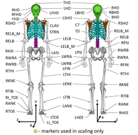
Head markers were hence updated from the left/right temple and back of head in the same horizontal plane. Instead, 5 markers are placed directly in the front, back, left, right, and top of the head for more consistent marker placement during collection, also while the test subject is wearing a head cap (see Figure 1). For feet, the toe marker is moved to the most distal land- mark of the first phalange, rather than placed over the second metatarsal head.
Scale factors for each axis of a segment are calculated, through a cus- tom OpenSim plugin, based on either marker pair component or resultant distances. The scale factors are calculated based on these marker pair dis- tances in the unscaled model markers versus the motion capture recorded markers. All model markers are allowed to shift to their recorded posi- tions on the subject during scaling rather than remaining fixed to the model default positions, using the “Adjust Model Markers” option in Open- Sim. Table 1 captures our chosen implementation for scale factor calcu- lation. For cases with multiple marker pairs, calculated scale factors are averaged.
The Digital Astronaut Simulation 229
Figure 1: Modified marker set used in data collection for scaling and inverse kinematics.Table 1. Marker pairs used to calculate segment non-uniform scale factors, by component (only right limbs listed; left limbs use corresponding marker pairs).
L Ulna RWRA, RWRB RELBY, RWRBY RWRA, RWRB L Radius RWRA, RWRB RELBY, RWRBY RWRA, RWRB
L Hand RWRA, RWRB RELBY, RWRBY RWRA, RWRB *Note: Indentation indicates parent/child relationship in the model topology.
Inverse Kinematics Improvements Even after initial model modifications, complex upper limb motions were challenging to capture, and IK artifacts such as arm ‘popping’ were often encountered. Foot kinematic accuracy also became more critical to define the BOS for various stances during exercise and stand-in place tasks. The following additional marker set, model, and method updates were tested to address this.
Medial elbow markers were added to data collections for use in IK.Clavicle and sternum markers were excluded previously due to frequent occlusion in early collections but are now reintroduced. Additionally, a temporary fifth phalange marker is included in a static pose as a landmark to aid verification of virtual markers, which are used to define the BOS boundary.
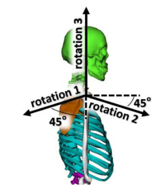
Arm axes of rotation at the 3 DOF shoulder joint were reoriented by 45 degrees to avoid gimbal lock singularities in the Euler angles (see Figure 2). The lower bounds of joint rotation limits were also adjusted for rotation_2 from −2.09 to −2.53 rad, for rotation_3 from −1.57 to −3.14 rad, for elbow flexion/extension from −0.79 to 0 rad, and for wrist flexion/extension from −2 to −2.22 rad. In addition, the pelvis rotation limits were unclamped and the clavicle extension angle was locked (i.e., reducing the joint to 2 DOFs).
Figure 2: Modified shoulder axes of rotation.
Computation of Ground Reaction Force, Moment, and Center of Pressure The following describes the implemented approach for calculating ground reaction force and moment, as well as the Center of Pressure (COP) location, based on motion capture data. A custom OpenSim plugin was created to compute the center of mass (COM) acceleration and the angular momentum time derivative. These are determined by the total force and moment from all the external forces acting on the body. When only the gravity and the distributed ground reaction forces are present, one can write:
Equation reproduced from the original PDF.
The Digital Astronaut Simulation 231
(vertical) gr (2)
d−→ L dt = −→r cm × m−→ g + −→r (cop) × −→ F gr + −→ M where −→r cm and −→ a cm are the subject COM location and acceleration, −→ L is the angular momentum, −→ F gr is the sum total of the distributed ground reac-
tion forces under the shoes, and −→r (cop) is the COP location in the ground plane. Once the OpenSim plugin has generated −→r cm, −→ a cm, and −→ L , one can find the ground reaction force via −→ F gr = m−→ a cm−m−→ g , and then adjust the two coordinates of −→r (cop) in the plane to fit the two horizontal components of the ground reaction moment (d−→ L /dt−−→r cm ×m−→ g ). The residual vertical part of this moment that is not captured by −→r (cop)×−→ F gr is referred to here as −→ M
(vertical) gr ; it may be nonzero because the vertical component of the moment of the distributed ground forces on the shoe soles may not be fully captured by the total ground reaction force applied at a single point −→r (cop).
The components of the calculated moment were filtered before deter- mining COP. This was performed with a Savitzky-Golay filter (Orfanidis, 1996) using a power of 4 and a frame length of 15 iteratively 3000 times.
VERIFICATION AND VALIDATION A data collection was performed with full-body motion capture (OptiTrack) and force platform measurement (AMTI) to test combinations of new marker sets and methods in scaling and inspect accuracy of calculated ground reac- tion forces, moments, and COP. “Unit Test” motions included dynamic range of motion for isolated joints, whole body swaying forward-backward and left-right both slow and fast, standing on toes and heels, toe touch followed by forward lean with torso flexion and arms hanging down, single leg stance, and swaying. “Pick Up Tasks” included variations of squatting to pick up an object from the ground. “Non-explosive Exercises” were deadlift, back squat, heel raise, overhead press, full squat with heels down, lunges forward- backward and left-right, and single leg squat. “Explosive Exercises” included hang clean and hang clean press variations.
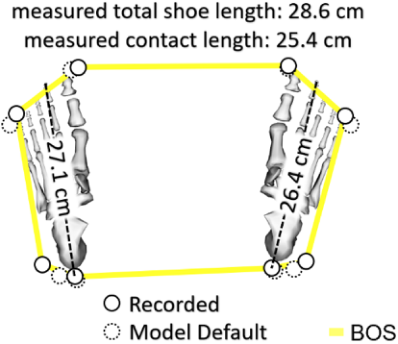
Scaling and Base of Support Improvements to model head scaling could be observed visually, as prior to implementing the modified marker set for head scaling, the scale factors frequently required manual adjustment to align with the recorded markers placed on the subject’s head. The modified marker set for BOS information allowed the foot to be scaled within the range of the manual measurements of the subject’s total shoe length and the portion of the subject’s shoe that contacts the floor (see Figure 3). These markers were also easier to place consistently and, along with virtual model markers, improved the accuracy of foot placement and hence BOS estimation.
Figure 3: Feet scaling and BOS comparison.
Inverse Kinematics With improvements, the average and maximum marker RMS errors were 1.25 cm and 2.43 cm, respectively, for a subset of traditional non-explosive exercises (back squat, deadlift, heel raise, and overhead press). The maximum individual marker error was 5.91 cm. OpenSim recommends an RMS error under 2 cm and the maximum marker error to be generally less than 4 cm. Although some individual markers have errors exceeding 4 cm, it was found that including them improved the agreement of COP results, so they were retained in the analysis.
Without these updates, some exercises suffered from IK artifacts. For example, the arms in hang clean press suddenly shifted orientation at a rate exceeding 10 deg/ms which resulted in erroneous peaks in force and moment curves and offsets in COP results. With the modifications applied to this trial, the combined arm joints never moved at a rate exceeding 2.5 deg/ms. The resulting mean and maximum COP errors for hang clean press were reduced by 25% and 4% respectively.
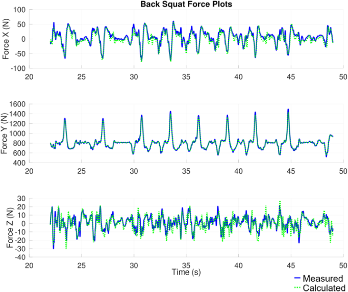
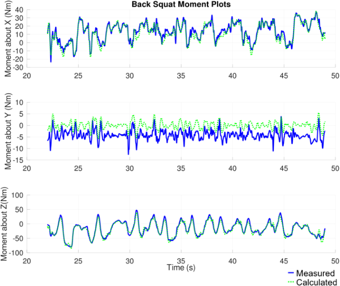
Ground Reaction Forces and Moments Calculated forces and moments agreed well with measurements over- all (see Table 2). Time history results are also shown for back squat (see Figure 4 and 5), which fell into the mid-range for error across all trials.
Table 2. Force and moment accuracy compared with force plate measurement.
Table available in the original PDF paper.
Overall (all trials) Force (N) Moment (Nm) X Y Z @X @Y @Z
Mean Error 5.8 4.4 2.2 2.4 4.9 3.3 Standard Deviation 4.2 6.8 2.8 2.8 1.9 3.7 Maximum Error 199.4 370.4 65.9 78.0 35.4 55.8
The Digital Astronaut Simulation 233
Figure 4: Back squat force comparison.Figure 5: Back squat moment comparison.
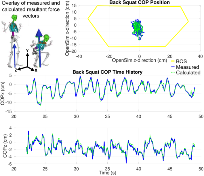
Center of Pressure The calculated COP results also met the needs of our applications, with sub- centimeter accuracy on average (see Table 3 and Figure 6). The quantified error could be applied as a threshold on the BOS boundary when flagging COP proximity.
Table 3. Accuracy of calculated COP versus force plate output.
Table available in the original PDF paper.
Types of Trials Mean Error (cm) Standard Deviation (cm) Maximum Error (cm) Unit Tests 0.50 0.48 7.29 Pick Up Tasks 0.63 0.50 4.20 Non-explosive Exercises 0.69 0.56 8.43 Explosive Exercises 0.76 0.82 11.36 Overall 0.56 0.54 11.36
Figure 6: Back squat COP comparison.
APPLICATIONS The Digital Astronaut Simulation team has engaged in many microgravity exercise related analyses since its origins including an evaluation of rowing with and without a seat, estimation of ground reaction forces from individ- ual feet (Thompson, 2018), and data collections with the Miniature Exercise
The Digital Astronaut Simulation 235
Device (MED-2) and Orion Flywheel Device in laboratory settings as well as in the Active Response Gravity Offload System (ARGOS) facility.
The most extensive application to date was in modeling and simulation to support the hardware development of the Vibration Isolation and Stabiliza- tion (VIS) system for the European Enhanced Exploration Exercise Device (E4D). Exercise data were collected, modeled, and output as a series of forcing terms (trajectory, inertial force, angular/linear momentum and deriva- tives at the human COM) which drive a multibody model of the iteratively designed VIS system (Quiocho, 2023). Interestingly, COP is used here as a tool for stability investigation. It must be the case that COP is always within one’s BOS. So, if a system force-moment balance places the COP outside the BOS, then the exercise conditions are deemed not dynamically feasible for microgravity. A modification would be needed by the crew member, exercise load or restraints, and/or the design of the integrated E4D/VIS system itself.
The concept was applied similarly to the evaluation of Extravehicular Activity (EVA) feasibility in lunar gravity (Lostroscio, 2020; Frenkel, 2021). There may be cases where the ground reaction force and moment on the feet cannot be directly measured, e.g., due to the particular experimental setup on Earth, or due to the desire to predict them in Lunar or Martian gravity environment via modeling and analysis. If one records the human motion tra- jectory via motion capture in the lab, and if one can assume the motion will be similar in the situation of interest, then one can use the method described to determine resultant force, moment, and COP.
The team also has expanded models to include external devices such as an upper arm offload system for reducing fatigue and representing reduced gravity during spacesuit testing on Earth (Nilsson, 2023). A custom analysis plugin was created to calculate offload force and shoulder torque and even estimate device kinematics when experimental data is not available (e.g., for a new device configuration). Theoretical subject models are also generated based on combinations of the existing subject models, ANSUR II database, body segment inertial parameters from literature (Dumas, 2007), and NASA or other anthropometric standards (Matari, 2022). Existing kinematic data from test subjects (typically similar in size) can then be applied to these the- oretical models to investigate edge case dynamic and volumetric impacts to a system or spacecraft.
DISCUSSION
In prior data without available medial elbow marker data, IK artifacts related to complex upper body motion were able to be retroactively mitigated on a case-by-case basis by applying one or more techniques (Bell, 2022): Upper arm markers could be included in generating IK results. Virtual medial elbow markers or virtual shoulder joint center markers could be created to encourage the proper arm orientation. The shoulder joint location in the clav- icle/scapula and humerus bodies could even be shifted such that it was more centered in the humerus body, decreasing the likelihood of the arm rotat- ing to unrealistic orientations. However, such adjustments were not always necessary or may require further validation.
Regarding scaling, in most of our applications, results only needed to rep- resent a realistic human rather than the exact individual so some difference in mass distribution would be acceptable. In the future, a residual reduction algorithm could be used to improve mass distribution, and the accuracy of subsequent ground reaction force and moment results.
Modifications in Evaluation To further improve results in new collections, some additional modifications are still in evaluation. Fifth phalange markers could be included on the toes during a static pose to aid in virtual marker placement for BOS definition, and lateral ball of foot markers could be used in IK to improve foot place- ment and inform BOS boundary when heels are raised. Forearm and right back markers remain unused for scaling and IK, but are maintained for data collection to aid automated marker labeling and trajectory gap filling in case of key marker drop outs. Additional markers could be placed on the hip to enhance motion capture gap filling techniques during RASI/LASI occlusions and improve accuracy of pelvis motion which has a significant impact on overall results. Additional techniques to enhance the consistent accuracy of pelvis scaling are also being investigated, such as using alternative marker pairs with knee or calculated functional hip joint centers. Thigh markers could be included during IK to better inform the orientation of the femur. In cases with large ranges of lower body motion, the pelvis Euler angle order could be adjusted to limit the likelihood of encountering gimbal lock. The feet subtalar ranges of motion may need to be increased (e.g., for walking).
CONCLUSION
With modifications to the full body model, including additional upper body joints and arm coordinate system rotation, along with refined methods for data collection and scaling marker sets, the kinematics of more complex exer- cises and upper extremity tasks were able to be more accurately captured and simulated. Furthermore, these adjustments are validated by the accuracy of computed ground reaction forces/moments and center of pressure, which was verified by force plate measurements. While the Digital Astronaut Simulation applies these tools primarily to spaceflight analyses, the model updates and estimation of external loads prospectively have broad applicability in reha- bilitation/reconditioning, sports science, and other human performance fields as well.
ACKNOWLEDGMENT
These efforts were built upon a foundation created by Ken Huffman. He remains in our memories and his developments continue to inspire.
The work described in this paper was performed entirely within the Soft- ware, Robotics, and Simulation Division of the NASA JSC Engineering Directorate.
The Digital Astronaut Simulation 237
REFERENCES
Bell, C., et al. (2022) “Adjusting a Full Body Model to Mitigate Inverse Kinematics Artifacts in OpenSim”, NASA Human Research Program Investigator’s Workshop. Bell, C., et al. (2022) “Accuracy of Center of Pressure Determination Via Motion
Capture”, NASA Human Research Program Investigator’s Workshop. Delp, S. L., et al. (2007) “OpenSim: Open-source software to create and analyze dynamic simulations of movement”, in: IEEE Transactions on Biomedical Engineering, 54(11), pp. 1940–1950. Dumas, R., et al., (2007) “Adjustments to McConville et al. and Young et al. body
segment inertial parameters”. Journal of Biomechanics 40, pp. 543–553. Frenkel D., et al. (2021) “Feasibility of Earthbound Motion in Lunar Gravity”, Human Research Program Investigator’s Workshop. Huffman, R. K., et al. (2019) “Improvement of Scaling and Inverse Kinematic Results
with Additional Upper Body Joints Added to OpenSim Rajagopal Model”, NASA Human Research Program Investigator’s Workshop. Lostroscio, K., et al. (2020) Lunar Surface Operations Modeling Using Digital Astronaut Simulation (Poster). Matari, F., et al. (2022) “Comparing Theoretically Scaled Biomechanical Models”,
NASA Human Research Program Investigator’s Workshop. NASA Standards Committee. (2016). NASA-STD-7009A: Standard for Models and Simulations. NASA. https://standards.nasa.gov/standard/nasa/nasa-std-7009 Nilsson, L., et al. (2023) “Modeling and Simulation of the Angel Upper Limb Offload
Device: Branching Into New Methods”, NASA Human Research Program Inves- tigator’s Workshop. Orfanidis, S., (1996). Introduction to Signal Processing. Englewood Cliffs, NJ: Prentice Hall. Quiocho, L., et al. (2023) “Modeling and Simulation for Exercise Vibration Iso-
lation and Stabilization System Design”, proceedings of 44th IEEE Aerospace Conference. Rajagopal, A., et al. (2016) “Full-Body Musculoskeletal Model for Muscle-Driven Simulation of Human Gait”, in: IEEE Transactions on Biomedical Engineering 63.10 (2016): 2068–2079. Seth, A., et al. (2018) “OpenSim: Simulating musculoskeletal dynamics and neuro-
muscular control to study human and animal movement”, PLoS Computational Biology, 14(7). Thompson, W., et al. (2018) “Estimation of Lower-body Kinetics from Loading Profile and Kinematics Alone, Without Measured Ground Reaction Forces”, proceedings of the 48th International Conference on Environmental Systems.
LISTED IN THE AHFE DIGITAL BOOKSTORE CATALOGUE
Explore the complete digital volume
Augmented, Virtual and Mixed Reality Simulation
Read this individual research paper free through the original publisher, or explore the full digital proceedings book.
ISBN 978-1-958651-94-0
Explore this ISBN in the AHFE Bookstore ↗Listed in the July 2026 bookstore catalogue; search by ISBN to confirm current availability · Digital book purchase optional