Alexander Mueller, Simon Buck, Fabian Schmiel, Temidayo Amosu (2023). Development of a Seating Buck for Ergonomic Vehicle Evaluation in VR Environment. In: Human Factors in Transportation. AHFE Open Access, vol. 95, pp. 20–26. https://doi.org/10.54941/ahfe1003788
Status quo: For the real and ergonomic validation of vehicle concepts, seating bucks and vehicle mock-ups are used in industry and research. The adaptability of these mock-ups with regard to the vehicle dimensions standardized in SAE J1100 or in the GCIE exchange list has proven to be very complicated in the past, so that seating bucks that can only be adapted to a very limited extent are still generally used in industrial applications today. The validation of the extents represented in the seating bucks usually takes place in an environment that can be experienced to a limited extent.Problem: The time required for the development and manufacturing of the seating buck is to be regarded as critical, since the development activities of the various disciplines continue on a steady basis. Due to the resulting time lag between the time of the definition of the seating buck display scope and the current development status, it cannot always be ensured that current data is tested in the seating buck. In addition, the limited representation of design-critical environmental scenarios (e.g. urban environment) leads to limited evaluation results.Method of Resolution: The objective is to provide a adaptable seating buck for vehicle evaluation, in which all tactilely and haptically perceivable features are represented in a realistic position and orientation and, at the same time, the realistic visual and acoustic perception of the vehicle and its environment is ensured. Since a variety of seating positions of different vehicle types and degrees of automation should be representable, the physical human-vehicle interfaces (e.g. steering wheel, seat and pedals) are interchangeable. The visual and acoustic perception of the vehicle or the environment is performed in a VR environment and is not the subject of this paper.The development of the seating buck for ergonomic vehicle evaluation in VR environment is discussed in detail, highlighting development, design and manufacturing aspects. A grid model is used as a basis, in which the position of the standardized heel point (AHP), that of the standardized hip point (SgRP) and that of the steering wheel center are described relative to each other and with standardized dimensions (cp. SAE J1100). In a next step, ranges could be identified for these dimensions that can be used to represent a wide field of vehicles available on the market. The development of adaptable modules for the pedals, the seat as well as the steering wheel is discussed and it is also explained how the drive for the adjustability of these modules was controlled, implemented and integrated into an overall design. The CAD model was digitally validated using the RAMSIS® digital human model (cp. Human Solutions). Finally, it is explained how exactly the vehicle dimensions can be controlled in the real model.
Current Situation and Problem For the real and ergonomic validation of vehicle concepts, seating bucks and vehicle mock-ups are used in industry and research. The adaptability of these mock-ups with regard to standardized vehicle dimensions has proven to be very complicated in the past, so that seating bucks that can only be adapted to a very limited extent are still generally used in industrial applications today. The validation of the extents represented in the seating bucks usually takes place in an environment that can be experienced to a limited extent.
The time required for the development and manufacturing of the seating buck is to be regarded as critical, since the development activities of the various disciplines continue on a steady basis. Due to the resulting time lag between the time of the definition of the seating buck display scope and the current development status, it cannot always be ensured that current data is
Development of a Seating Buck for Ergonomic Vehicle Evaluation in VR Environment 21
tested in the seating buck. In addition, the limited representation of design- critical environmental scenarios (e.g. urban environment) leads to limited evaluation results.
Objective The paper aims to show how a fast adaptable and variable seating buck for driver vehicle evaluation can be systematically designed, in which all tactilely and haptically perceivable features are represented in a realistic posi- tion and orientation and, at the same time, the realistic visual and acoustic perception of the vehicle and its environment is ensured. Since a variety of seating positions of different vehicle types and degrees of automation should be representable, the main physical human-vehicle interfaces (especially stee- ring wheel and seat) are interchangeable. The visual and acoustic perception of the vehicle or the environment is performed in a VR environment and is not the subject of this paper.
METHODS
For the development of the variable seating buck, the variable adjustment parameters as well as their dimensional ranges for the mapping of diffe- rent vehicle types have to be determined first. In the next step, a parametric associative CAD grid model is built, which is then extended to include the supporting structure, the adjustment actuators and the assemblies of the physical human-machine interface as well as those for the VR applica- tion (force feedback elements). Finally, the seat box is being measured and calibrated.
Selection of Variable Setting Parameters The conception of the vehicle dimensional layout takes place in the early phase of vehicle development and is based on vehicle dimensions that are standardized nationally, internationally and also across manufacturers in the form of a special exchange list (DIN 70020-1; SAE J1100; GCIE exch- ange list). Different vehicle concepts can be represented as a function of these dimensions. The following dimensions in particular are decisive for the representation of the driver’s workplace: A18 Steering Wheel Angle, Y-Plane A47 Accelerator Angle H17 Accelerator Heel Pont (AHP) to Steering Wheel Centre (SWC, Z-dimension) H30-1 AHP to Seating Reference Point (SgRP) – Front (Z-dimension) L11 AHP to Steering Wheel Centre (SWC, X-dimension) L53-1 AHP to SgRP (X-dimension) W8 AHP Y-Coordinate W20-1 SgRP Y-Coordinate
Definition of the Design Framework In order to determine the adjustment ranges of the vehicle dimensions listed above, data of current vehicle concepts is analysed (autograph dimensions, A2MAC1). The main objective is to use the seating buck to represent vehicle
concepts with different seating heights. On the one hand, vehicles with low seating heights, i.e. sports vehicles, should be representable; on the other hand, vehicle concepts with high seating heights (SUVs and Vans) should be made experienceable. The dimensional ranges of the above-mentioned vehicle dimensions that enable the depiction of these different vehicle concepts are listed in Table 1.
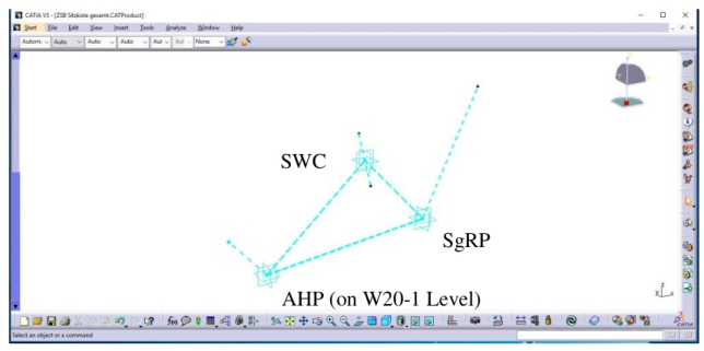
Development of a Parametric Associative CAD Grid Model The basis of the design is a parametric associative CAD grid model, which can be used to adapt the accelerator heel point (AHP), seating reference point (SgRP) as well as the steering wheel centre (SWC) depending on the previously defined dimensions in the dimensional ranges shown in Table 1 (cp. Figure 1).
Development and Integration of Structure and Assemblies of the Physical Man-Machine Interface Based on a grid model, the first step is to design a supporting structure that holds the assemblies of the physical man-machine interface. A proven and standardized building kit with a large number of structural elements and linear guideways is used to design the structure. In the first step, the assem- blies of the physical man-machine interface are taken from vehicles currently
Table 1. Adjustment ranges of the variable seating buck.
Table available in the original PDF paper.
Dimension Minimum Maximum A18 14
40
A47 42
55
H17 578 mm 744 mm H30-1 180 mm 404 mm L11 289 mm 517 mm L53-1 761 mm 923 mm W8 187 mm 226 mm W20-1 321 mm 401 mm
Figure 1: Parametric associative CAD grid model.
Development of a Seating Buck for Ergonomic Vehicle Evaluation in VR Environment 23
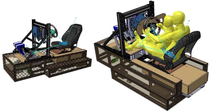
available on the market. In doing so, it is important that these assemblies are as vehicle concept-neutral as possible. The interface to these assemblies is designed in a manner that these assemblies can be exchanged with little effort if necessary. For the Z adjustment of the seat, the angle adjustment of the steering wheel and that of the pedals, the modular system mentioned above cannot be used due to a lack of supply. The Z adjustment of the seat is realized by means of a lifting table available on the market, which is integra- ted into the supporting structure. A ring segment guide is used for the angle adjustment of the steering wheel, so that the steering wheel angle can be adju- sted around the centre of the steering wheel. The adjustment of the hanging pedal set is implemented with a lever mechanism. Force feedback elements are installed to connect the variable seating buck to the VR environment (cp. Sensodrive). On the one hand, a force feedback element for the stee- ring wheel is installed, on the other hand, a pedal set with accelerator pedal and brake pedal. Figure 2 shows the supporting structure, the guidance and force feedback elements and the assemblies of the physical human-machine interface, as well as the validation of threshold setting values with respect to the collision potential with the digital human model RAMSIS® (cp Human Solutions). A simple driver collective with proven spread of anthropometric data is chosen for this purpose (5th percentile woman - 95th percentile man, cp. Bubb, et. al., 2015).
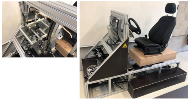
Development and Integration of Actuators The seating buck is adjusted on a 12 V basis. An Arduino microcontrol- ler (Arduino) is used to control the actuators. For the linear adjustments, standardized electric cylinders are used, which have proven themselves in building automation and in which displacement sensors are already integra- ted. Adjustment of the steering wheel angle is performed with a windshield wiper motor and a spur gear. The control is done with a potentiometer inte- grated in the gearbox (cp Figure 3). An additional potentiometer is installed to control the lift table.
Figure 2: CAD modell of the variable seating buck.Figure 3: Steering wheel adjustment module and seating buck.
Measurements and Calibration After the seating buck has been assembled, it is measured and calibrated. An H-point measuring machine standardized according to SAE 826 (SAE 826) is used for this purpose. The measurement is performed with a FARO measuring arm. Calibration is performed by first displaying threshold vehicle dimensions with the seating buck before measuring them. Figure 3 shows the assembled and variable VR seating buck.
RESULTS
By varying the above-mentioned vehicle dimensions, the seating buck can be used to represent the driver’s workplace of different vehicle concepts. Table 2 shows how precisely the vehicle dimensions can be adjusted with the seating buck.
Table 2. Deviations of the measured values from the target values.
Table available in the original PDF paper.
Dimension Min. Target Value / Deviation Max. Target Value / Deviation A18 14
/ +0.1
40
/ + 0.2
A47 42
/ −2
55
/ −5
H17 578 mm / +0.7 mm 744 mm / +0.5 mm H30-1 180 mm / +5.6 mm 404 mm / + 6.7 mm L11 289 mm / +3.7 mm 517 mm / −0.5 mm L53-1 761 mm / −12.3 mm 923 mm / +0.1 mm W20-1 – W8 170 mm / + 5.4 mm 134.6 mm / −2.1 mm
DISCUSSION
The dimensional accuracy of the adjustable steering wheel position and stee- ring wheel angle is very good. The steering wheel height and the distance of the steering wheel centre from the AHP can be approached with small and tolerable deviations, and the steering wheel angle is displayed with virtually
Development of a Seating Buck for Ergonomic Vehicle Evaluation in VR Environment 25
no deviation. The position of the SgRP relative to the AHP is acceptable in terms of height, but can be further improved to a good value after further cali- bration. The X position of the seat relative to the AHP currently shows too large an error due to the accuracy of the displacement encoder built into the electric cylinder. It is planned to install an external position encoder, which has already proven its worth in positioning the seat in the Z direction. The position of the pedal set can be approached with good accuracy, the pedal angles are also to be recalibrated so that they can be set with good accuracy. Conceptually, the adjustment of the pedal set is subject to error, since in rea- lity it does not rotate around the AHP. When designing the kinematics, the invariant distance between the Ball of Foot and the AHP must be taken into account.
CONCLUSION
The results show that the procedure outlined is generally target-oriented, and the seating buck can be adapted with sufficient accuracy.
Simplifications were also accepted deliberately in the definition of the adjustment parameters. For example, the pedal angles cannot be adjusted independently, nor can the Y coordinate of the steering wheel (SWC) be manipulated independently of that of the seat (SgRP). The seat also curren- tly cannot be rotated about the Z-axis. Future concept evaluations using the seating buck will show whether the assumptions that led to these simplifi- cations can be confirmed. However, the modular design of the seating buck accommodates a possible modification of the adjustment parameters and/or their adjustment ranges at a later time.
REFERENCES
A2MAC1, 2023. Decode the future, [Online]. Available at: https://www.a2mac1.co m/ [Accessed 12.01.2023]. Arduino, 2023. What is Arduino? [Online]. Available at: https://www.arduino.cc/
[Accessed 12.01.2023]. autograph dimensions, 2023. Unternehmen. [Online] Available at: http://www.auto graph.de/index.php?id=5 [Accessed 12.01.2023]. Bubb, H., Bengler, K., Grünen, R. & Vollrath, M., 2015. Anthropometrische Fahr-
zeuggestaltung. In: Automobilergonomie. Wiesbaden: Springer Vieweg, p. 182. DIN 70020.1, 2006. – Entwurf: Straßenfahrzeuge – Kraftfahrzeugbau – Teil 1: Personenkraftwagen, Begriffe, Grundlagen, Bestimmungen, Maßkurzzeichen. Avai- laible at: https://www.beuth.de/de/norm-entwurf/din-70020-1/89165849 [Acces- sed 12.01.2023]. GCIE, 2023. Global Car Manufacturers Geometrical Information Exchange Plat-
form for series production vehicles [Online]. Available at: https://www.gcie.net/h ome [Accessed 12.01.2023]. Human Solutions GmbH, 2023. Ramsis allgemein. [Online] Available at: https://www.human-solutions.com/de/produkte/ramsis-allgemein/i ndex.html [Accessed 12.01.2023]. SAE J826, 2021. Devices for Use in Defining and Measuring Vehicle Seating Acco-
modation. Revised. Published by SAE International in United States. DOI: https: //doi.org/10.4271/J826_202106. Available at: https://www.sae.org/standards/co ntent/j826_202106/ [Accessed 12.01.2023].
SAE J1100, 2009. Ground Vehicle Standard. J1100_200911. Revised. Published November 20, 2009 by SAE International in United States. DOI: https://doi. org/10.4271/J1100_20091. Available at: https://www.sae.org/standards/content/ j1100_200911/ [Accessed 12.01.2023]. Sensodrive, 2023. Force Feedback Products [Online]. Available at: https: //www.sensodrive.de/produkte-leistungen/force-feedback-lenkraeder.php [Acces- sed 12.01.2023].
LISTED IN THE AHFE DIGITAL BOOKSTORE CATALOGUE
Explore the complete digital volume
Human Factors in Transportation
Read this individual research paper free through the original publisher, or explore the full digital proceedings book.
ISBN 978-1-958651-71-1
Explore this ISBN in the AHFE Bookstore ↗Listed in the July 2026 bookstore catalogue; search by ISBN to confirm current availability · Digital book purchase optional