William L. Gillis, Elizabeth A. Cudney (2019). Applying the House of Quality to the New-Building Construction Commissioning Process. In: Advances in The Human Side of Service Engineering. AHFE Open Access, vol. 8. https://doi.org/10.54941/ahfe100271
Commissioning (Cx) is a quality process for building construction used to verify that the Owner’s Project Requirements (OPR) are being met by the final design and construction (D&C). The goal is to confirm that each phase of the project is linked back to the OPR through quality assurance methods. Leadership in Energy and Environmental Design (LEED) certification is an OPR and can contribute to difficulties within the D&C process. The LEED rating system offers numerous point opportunities that span the full range of design disciplines. It is difficult to quickly understand how a design decision made by one discipline impacts another discipline’s goal(s) for maximizing LEED points in their respective areas. The House of Quality (HOQ) tool of the Quality Function Deployment (QFD) methodology can provide a means of comparison among the OPR, the proposed design, and the design impacts among the LEED credits. This paper will introduce a proposed four-phase QFD model that has been specifically modified and tailored for use by the Commissioning Authority through all phases of D&C process. It will then focus on the methodology for developing the first phase of the model, which is expanded for projects seeking LEED certification. The remaining three phases of the Commissioning QFD are discussed elsewhere. The first phase or pre-design phase will consist of two HOQ matrices for LEED projects. The first HOQ will be used to assist in identifying the LEED credits to be included in the OPR and to understand the design impacts among the LEED credits selected. The second HOQ will evaluate the alignment of the architect/engineer team’s Basis of Design (BoD) with the OPR, as well as identify the impacts among the OPR and the impacts among the BoD.
The construction of a new non-residential building can represent one of the largest investments any business will face. With most investments, it is desired to maximize value and minimize cost and this of course holds for most new building construction. Trends are driving building designs and construction methods that are considered “sustainable” and/or “green,” however the benefits of going sustainable/green vary greatly depending on the needs of each potential building owner.
In the case of a traditional design/bid/build construction process there are distinct phases in the building lifecycle. During each phase certain groups have responsibility for deliverables and those are generally structured as follows: Pre-design phase – owner and architect (and often the engineers); Design phase – architect and engineers with owner feedback at design reviews; Construction phase – general and sub-contractors with oversight by the owner’s construction manager (CM); and Operations & Maintenance (O&M) phase – the maintenance team assigned to the building. Typically the owner’s project manager (PM) will be involved from pre-design through occupancy; however, the PM may have minimal involvement other than schedule and budget concerns once construction begins and the CM is involved. It is unlikely the PM will be involved with the project after occupancy, which leaves sole responsibility of the O&M phase to the O&M staff. If a building is to be sustainable, project emphasis must continue beyond construction into the O&M phase of the building’s lifecycle. This becomes difficult when project oversight is relinquished at turnover. The commissioning authority (CxA) is likely the only player with project responsibilities beginning at conception and continuing through the warranty period.
Cx is an owner initiated process that is expected to bridge all phases of a D&C project, including O&M, by verifying that D&C processes meet the OPR. As each team hands off to the next, the commissioning authority (CxA) will confirm that the preceding team is providing the following team with the necessary information to complete their responsibilities in a manner that meets the OPR. This begins with the owner, meaning the OPR needs to be as detailed and complete as possible so the designers understand what they are to provide.
Next, the designers must produce construction documents that are adequate for the contractor to build what is designed. The contractor must provide submittals for the materials and equipment which confirm the selections meet the drawings and specifications. Then the construction must be completed as specified in the construction documents.
Finally, the training and documentation provided to the O&M staff must provide a clear picture of what they will be operating, how it was designed to operate, why it was designed that way, and how it should be operated and maintained. Without the O&M staff having this knowledge it is unlikely the building will be sustainable. The O&M staff is basically stuck with what is turned over to them when construction is complete. If the process of linking all activities back to the OPR fails in any previous phase it is unlikely they will be able to operate the building as expected. Figure 1 presents the major Cx activities in a typical new-building construction project as proposed by ASHRAE Guideline 0-2005. The CxA will have the responsibility of ensuring these activities are realized and that each meets the expectations of the OPR. As there is a handoff of responsibilities at each phase, the CxA ensures and verify that each handoff is sufficient to meet the OPR. Though building commissioning is not a new concept and is the focus of much work by Cx organizations and practitioners, there are still weaknesses in the process that can be addressed.
As part of an effort to prequalify firms for future project needs, a formal request for quote (RFQ) for Cx services was sent to numerous Cx consulting firms. Thirteen formal responses were received. One key question asked within the RFQ was: “How will the basis of design be verified with regard to the owner’s project requirements?” None responded with any type of process for how they would accomplish this, simply that it would be done. An assumption made was that they either did not have a formal method or they did not wish to disclose. Regardless, there is no published methodology for this process and firms or persons entering the field are left to figure it out as they go.
This is seen as a weakness in the process and serves as partial motivation for this research. The reason for contracting a third-party representative, the CxA, is for the owner to get some hard documentation that all of the verification is being accomplished and is sufficient. Without some type of method used by the CxA, the owner is left with the same uncertainty as would be if they simply took the word of the architect/engineer (A/E) team and contractors. And the question remains – “when this project is complete, will I get all that I asked for and am expecting?”
A deviation this proposed methodology takes from ASHRAE Guideline 0 is moving “verify the BoD meets the OPR” from the Design Phase to the Pre-Design Phase - this a critical step and design should not begin until the owner and A/E team are confident the BoD and OPR are in alignment.
Pre-Design Develop Phase
OPR Cx Plan
Verify Design
Develop Construction
Phase
BoD meets
Design Reviews
Develop Cx Specs Checklist
Define Training Requirements
OPR
Drafts
Verify Systems
Construction
Verify Submittals
Verify Construction
Verify Training
Develop Functional
Phase meet the
of O&M
Tests
through Functional
OPR
Checklist Completeness
Staff Tests
Seasonal Warranty
Lessons
O&M Phase Testing
Review Learned
Figure 1. Commissioning activities
Figure available in the original PDF paper.
QUALITY FUNCTION DEPLOYMENT Quality function deployment (QFD) has traditionally been used by companies for product development and manufacturing to determine the best design options, manufacturing processes, costs, and level of quality among others. The matrices of the four-phase QFD model are designed to bridge the major phases of product development and manufacturing. Phases proposed by Clausing (1994) are House of Quality, Part Deployment, Process Planning, and Operations Planning. The goal is to ensure that the needs of the customer are translated through to the final product.
Hauser and Clausing (1988) asked, “Design is a team effort, but how do marketing and engineering talk to each other?” This is a question that many in the manufacturing industry might answer, “not well.” A similar question could be asked within the construction industry, “Design is a team effort, but how does the owner and A/E team talk to each other?” Many in the construction industry might answer same way, “not well.” This is no fault of either party as they typically do not speak the same language. Many owners do not understand the technical jargon of architects and engineers. With product development, marketing is typically adept at determining what the customer might want in a product. With building design, the architect typically has the first contact with the owner and most architects are proficient with the programming effort required to determine what the building should be, however much can be missed when it comes to the building systems. Hauser and Clausing (1988) illustrate how quality function deployment and the house of quality (HOQ) can provide a solid method of communication between marketing and engineering, which then continues downstream to the manufacturing and quality assurance activities. A similar method using the HOQ and QFD can be adapted to the D&C Cx process.
The HOQ is a tool within the QFD process which provides a means of matching the product’s design with the voice of the costumer or customer requirements. Figure 2 illustrates the basic HOQ. Customer requirements are what the customer desires of a particular product based on marketing studies. The design response is how the designers will meet the needs of the customer. Design correlations are used as a means of understanding if one design response has an impact on another design response. The body of the matrix holds the relationships, or how well each design response addresses the customer requirements. The marketing matrix and design data matrix are used by the marketing and design teams for developing and prioritizing the whats and hows. In short, QFD is designed to gather the customer’s needs and desires of a product, weigh those needs and desires against the needs and desires of the company, verify that engineering designs the product to those requirements, and verify that manufacturing can produce the product as designed. The goal is a product that will appeal to as many customers as possible.
Figure 2. Basic HOQ
Figure available in the original PDF paper.
Quality Function Deployment in the Construction Industry Researchers over the past several years have demonstrated ways QFD can also be a beneficial tool for the construction industry. Mallon and Mulligan (1993) present QFD as a means for meeting the customers’ requirements in construction projects, providing an example of such for a computer workroom. Eldin and Hikle (2003) conducted a pilot study, using the design of a classroom as a case, to determine the effectiveness of using QFD as a means of developing conceptual designs in the preliminary phase of construction projects. Ahmed et al. (2003) utilized QFD for a civil engineering capital project. Yang et al. (2003) integrate fuzzy set theory into the QFD process for use as a decision making aide in construction design. Alarcon and Mardones (1998), Gargione (1999) and Abdul-Rahman et al. (1999) used it in the design phase to capture the customer needs. Dikmen et al. (2005) examined a completed building to capture customer needs for marketing purposes. Delgado-Hernandez et al. (2007) considered nursery development/design. Each of these are primarily looking at the design and capturing the needs of the customer. These processes appear to be structured for use by the design team or could be used by the owner where the owner would then specify the design criteria. This may have a tendency to constrain the design creativity. Kamara et al. (2000), Pheng and Yeap (2001), Lee and Arditi (2006), and Lee et al. (2009) used QFD as a tool for concurrent engineering and design/build applications.
The objective of this paper is not to regenerate how QFD could be used by a design team within the construction industry as a means to improve their final product (design only), rather to introduce a QFD model that has been specifically tailored for use by the CxA during the entire D&C process and to focus on the development of the first phase of the model. This will consist of two HOQ matrices, one specifically for LEED projects and one serving as the Pre-Design HOQ.
The OPR is considered a living document and is subject to change throughout design and construction. Changes may occur at any time during the project and any changes must be approved by the owner and be updated by the CxA. The BoD is also a living document and will very likely change as the design progresses and should also be updated as needed. The Pre-Design HOQ has been adapted and modified to provide a method to analyze any proposed changes to the OPR or the BoD and to quickly determine how the change will affect the other OPR and BoD criteria.
The proposed commissioning QFD model is presented in Figure 3. This model was developed to integrate with the Cx process recommended in ASHRAE Guideline 0. The four phases of the model link the major design, construction, operations and maintenance, and Cx activities back to the OPR. For these activities to be linked between phases the information in the hows area of the previous matrix will transfer to the whats area of the following matrix. The whats and hows for each matrix are as follows:
Pre-Design Phase: OPR (what), BoD (how); Design Phase: BoD (what), Design [broken down by division, system, sub-system, and components] (how); Construction Phase: Design [broken down by division, system, sub-system, and components] (what), Construction [broken down by sub-contractor and components installed] (how); and finally, O&M Phase: Construction [broken down by sub-contractor and components installed] (what), Documentation [construction checklists, functional performance tests, training, O&M manual, systems manual] (how). These will effectively tie all activities back to the OPR and provide a solid foundation for the O&M staff at occupancy.
METHODOLOGY FOR THE PRE-DESIGN PHASE Building the Pre-Design HOQ
The first step in the Cx process is assisting the owner with developing the OPR. There are many methods for assisting the owner in developing the OPR, some of which might include workshops with key stakeholders, questionnaires, group meetings, or nominal group technique. Based on the focus of this research, these methods will not be discussed here with the exception of those OPR that include LEED certification.
Information gathered from the OPR development workshops will be entered into the marketing matrix and whats sections simultaneously. This will provide an opportunity to prioritize the OPR based on importance to the owner.
Once the OPR has been established, prioritized, and approved by the owner the information is finalized in the whats area of the house. The approved OPR along with the priorities should also be provided to the A/E team to use as a reference and compliment their programming and design effort.
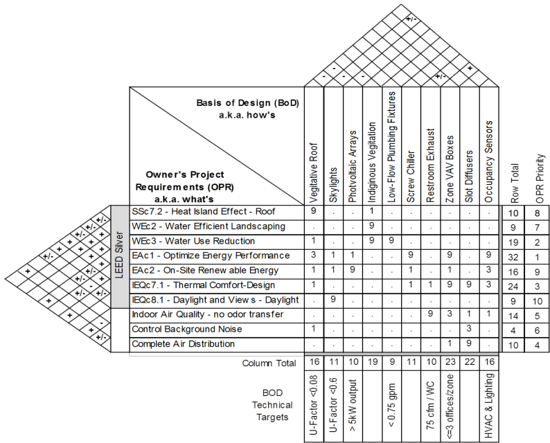
The BoD, based on the approved OPR, will be generated by the A/E typically during their schematic design phase and will be provided to the owner and CxA. The BoD is entered into the hows area of the house. Each project will have a different OPR and BoD; therefore, Figure 4 presents the Pre-Design HOQ in a much abbreviated state. Hypothetical OPR and BoD have been added for illustration purposes. One specific addition here is the LEED requirement. In this example, ‘LEED-Silver’ has been added as an OPR along with some possible credits. The LEED requirements and how to deal with them will be discussed later.
Figure 4. Pre-Design HOQ
The body of the matrix will be used by the CxA during the review of the BoD to verify it meets or addresses each of the OPR. Using a numbering scheme of 9 (strong relationship), 3 (medium), and 1 (weak) in each cell to specify how well each BoD meets a particular OPR will be used. This numbering convention has been utilized by many researchers and is recommended by Cohen (1995). A “.” is used to populate a cell in which the combination has been reviewed and found to have no relationship. This is meant to reduce the duplication of work which may occur if the cell is left blank and multiple people are conducting the review.
It is important to understand that these entries are the professional opinion of the CxA and are not intended to be a critique of the design per se, rather to identify points of discussion between the owner and design team if it appears some OPR are not well represented in the design. The values in each row and column will be summed to identify which OPR are well addressed by the BoD and how well each BoD is addressing the OPR as a whole.
The design correlations area (roof) of the HOQ is used to understand the impact, negative or positive, one design criteria has on another. The methodology for the roof will be explained with the development of the LEED HOQ.
The addition of a correlation matrix to the OPR is specifically for the CxA to use while assisting the owner and A/E team align the OPR and BoD. This correlation matrix identifies the impact(s) a change in one OPR will have on another OPR. The CxA may identify OPR that have not been well addressed by the BoD. During discussions between the owner and A/E the owner may be asked to change the OPR. Using the correlation matrix the owner can now quickly understand how that change might affect other OPR. This is particularly useful for LEED projects.
Building the LEED HOQ There are many combinations of credits that can be utilized to accomplish an owner’s LEED certification goal, but the combination that best fits the OPR and the owner’s definition of value is a question that must be answered early in the process. This is complicated and requires much coordination, cooperation, and communication.
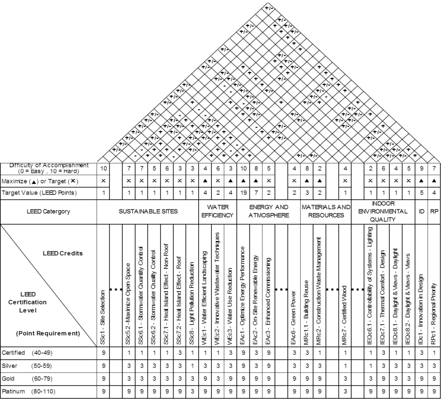
At this point all of the certification levels and the required points are added as OPR, as the final level that will be achieved is not known this early in the process. The LEED credits will now be added as BoD responses. Figure 5 represents an abbreviated LEED HOQ. The remaining credits would be entered in the same manner, but are not able to be displayed in the format of this document. Therefore, an abbreviated version is provided. The associated points for each credit are added to the target value (LEED Points) row above the credits categories. LEED categories and credits along with the associated points can now be quickly referenced.
Figure 5. LEED HOQ
The row above the target value is used to symbolically represent whether the target value should be maximized or is the target. Many credits only offer one point level (all or nothing) while others offer a range of points. If the points are “all or nothing” an “[Equation or mathematical symbol available in the original paper PDF]” is used to indicate this is the target. If the points are a range a “[Equation or mathematical symbol available in the original paper PDF]” is used to identify that the goal is to maximize points. The next row above is used to represent the difficulty of achieving the target or goal. In this case the CxA’s experience in the D&C fields would be used to rank the difficulty of each credit from 0 – 10, with 10 representing “extremely difficult.” Primarily the difficulty represents the level of cost, time, and resources required to accomplish the associated LEED points. Each project will have its own level of difficulty for achieving certain credits so this section will vary from project to project. The values are not critical to achieving a particular level of LEED certification, but are useful in engaging the owner in the process of determining which credits are truly important to them and ultimately which should be included in the OPR.
The matrix between the certification level and credits is now populated. This can only be completed with some understanding of the LEED process and the requirements for achieving the LEED credit points. Generally though, without that knowledge, it can easily be seen that in order to achieve LEED Platinum, which requires a minimum of 80 points from the available 110, attempting most of the credits will be necessary. Achieving 80 points is not an easy accomplishment.
The same numbering scheme of 9 (high), 3 (medium), and 1 (low) will be used to populate the relationships matrix, but are now used to indicate how important it might be for this credit to be attempted in order to meet the level of certification. There is no mathematical significance to these numbers, but again is simply a visual strategy to engage the owner in the process and to provide a simple method for understanding the difficulty of reaching each successive certification level and that some credits that the owner would not have pursued will now be needed if trying to reach the next level. Again analyzing the opportunities or necessities for LEED Platinum, it can be seen that nearly every credit may have to be attempted to accomplish 80 points, particularly if all the available points for the credits having a range of points are not achieved. In the Pre-Design HOQ, this matrix makes it simple to identify if a particular OPR is being adequately addressed by the design team. With the LEED HOQ this is simply providing insight into the difficulty of achieving certification.
One of the most valuable components of the LEED HOQ is the roof, as it represents the affects, either negative or positive, one credit has on another. It offers a quick visual for a CxA and owner to understand the impacts one discipline’s decision will have on another discipline’s work.
The roof is laid out to capture the relationship between any two LEED credits. If one credit is taken in a positive direction, meaning the design is attempting to maximize the points for that credit, the roof indicates the impact on another credit. If it has a negative impact a “-“ is placed in the cell, positive impact a “+” is used, and if both positive and negative a “+/-“ is used. The roof cannot be populated without an understanding of the requirements of achieving each LEED credit, design practices of architects and engineers, and general construction. To populate the roof each credit was evaluated and compared to each of the other credits. A determination was made as to how the credits impacted one another. Notice the roof is heavily populated with “+/-“. This indicates that depending on which credit is taken to the side of maximizing points, the other credit will realize a positive or negative impact. The specific impacts will only be determined by the designers involved in each project, but this provides a quick reference for the CxA and owner to understand that conflicts do exist and if a +, -, or +/- is found in the cell then questions to the design team are warranted. This will be especially useful in selecting which credits to attempt (i.e. how will the decision to select one credit impact the scorecard as a whole?) and if late design changes are proposed (i.e. if the design change proposed changes one credit how does it impact the other credits?).
Some design decisions may affect or impact more than one design area or credit. In this situation a chain reaction of impacts occurs. An example might be: Sustainable Sites, Credit 7.2, Heat Island Effect – Roof, exposes a number of relationships that should be considered. There are many design strategies that may achieve this credit but let’s look at the vegetative or “green” roof option. First, the cost to install a “green” roof would need to be compared to a more conventional roof which would also accomplish the credit (budget impact). Second, the “green” roof will likely have greater mass and may require an increased structural system in the building (budget impact and possibly a reduction of the interior volume, which reduces the available space for the building systems and occupants). Any roof that qualifies for SS Credit 7.2 will reduce the heating and cooling loads on the building and, therefore, reduce the amount of energy required to maintain thermal comfort (life-cycle cost). Another advantage with reduced heating and cooling loads is that the equipment required to heat and cool the building can be reduced (first cost reduction).
Since the HVAC system is smaller, so too will be the electrical system necessary to supply the equipment (smaller electrical gear and lower first-cost). This is a vegetative roof so it will require irrigation to keep the plants alive (higher water usage and utility bill). This will negatively affect the water efficiency of the building (WE Prerequisite 1). With this there is an opportunity to plant indigenous vegetation and to attempt Water Efficiency (WE) Credit 1, Water-Efficient Landscaping or SS Credit 5.1, Site Development – Protect and Restore Habitat.
Adding a skylight(s) to this roof will reduce the area of the vegetation, the heat island effect will still be reduced, the required irrigation will be reduced, but now the additional sun introduced through the skylight will contribute to achieving Indoor Environmental Quality, Credit 8.1, Daylight and Views – Daylight. However, the insulating factor of the vegetative roof is now reduced and solar heat gain is introduced, which will increase the heating and cooling load, HVAC system requirements, and electrical system requirements.
The HOQ roof as designed for product development cannot take into account all of these impacts at one glance, but does still have the ability to expose the possible path of the affects and provides a method to navigate the possibilities. Knowing that one technical response will have an effect on another can still lead to the understanding that a third and fourth response is affected.
LEED certification will likely be only a small part of the OPR, but much of the design directed towards meeting the other OPR can contribute to meeting the LEED certification. Based on other OPR some of the LEED credits can or will be eliminated. For example, the owner may have decided that in no circumstance shall the new building be located on a property that is considered a brownfield site. This would eliminate LEED opportunity Sustainable Sites, Credit 3, Brownfield Redevelopment. This is a simple and obvious example, but as some credits are eliminated it reduces possible impacts that might be imposed on other credits.
Additionally, some credits may be eliminated because given certain circumstances they are impossible to obtain. Reviewing the LEED HOQ roof it can quickly be seen that nearly all of the Sustainable Sites (SS) credits will have positive or negative impacts on each other. The site selection is critical to many other credits and may be outside the control of the design team. Often an owner will have purchased a piece of property long before contacting an architect, design team, LEED AP, or CxA. The location and size of the property will immediately either eliminate the possibility of achieving or promote achievement of other credits. For example, if a site is selected in a rural setting, outside city limits perhaps, it is likely that it will eliminate the possibility of SSc2, Development Density and Community Connectivity and SSc4.1, Public Transportation Access. What begins to happen is that the list of possible credits shortens and the need to maximize points of other credits heightens. Looking at the relationships area of the LEED HOQ it can be seen that these numbers will have to increase as fewer possibilities are available. Now many if not all of the relationships will be rated as a 9. It may also be seen that it is impossible to achieve LEED-Platinum or even Gold.
When this process is complete and the LEED certification level and credits to be attempted have been determined, the credits are added to the OPR as a sub-requirement to the LEED level. The complete OPR, including the owner’s preferred LEED credits, can be presented to the design team. Now the BoD presented to the owner by the design team will be directed towards meeting those specific LEED credits as well as the other OPR. It is recommended that the full LEED HOQ (all of the credits are listed) be kept intact for future review of impacts caused by late design change proposals. The CxA and owner can quickly go back to the roof and determine if a proposed change will negatively impact the original credits, thus providing a greater opportunity to determine if the change has value to the owner.
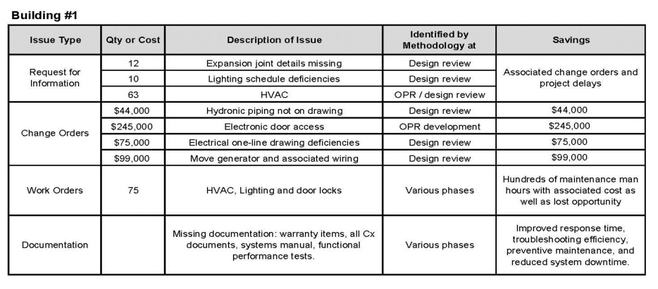
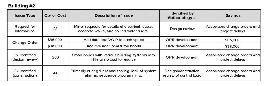
CASE STUDY The complete Cx QFD model (the final three phases are discussed elsewhere) was developed to verify that the OPR and the needs of the downstream customers are adequately addressed by the previous team. It links each of the critical phase activities back to the OPR while working toward reducing issues at any phase of the project. The project issues of two recently completed buildings were investigated and applied to the model to determine when each issue would have been discovered or avoided and the expected savings associated. Each of the projects received Cx with differing results. All issues were considered, and included: RFIs, Change Orders, ASIs, Warranty Issues, Work Orders (after occupancy and the warranty period), and Cx identified issues.
Building 1 was a major renovation project that included a new addition of approximately 33% of the total 90,000 sq. ft. The project budget was $26M. Building 2 was also a major renovation of 30,000 sq. ft. and a project budget of
$4M.
The issues and quantities of each are presented in Figure 6. Much of the Cx documentation for Building 1 could not be located. The major issues and the results of applying those issues to the model are presented in Figures 7 & 8. It can be seen that there are several issues that would have been eliminated in the pre-design phase using the model.
Figure 6, Issues and quantities
Figure 7. Building #1major issuesFigure 8. Building #2 major issues
LIMITATIONS The length of time and manpower to develop the Pre-Design HOQ could pose a problem for some teams. A very simple example was presented here, but the HOQ for a complete building will be sizable. Significant resources may need to be available to ensure other project activities are not delayed. To develop both the LEED HOQ and the OPR of the pre-design HOQ there will have to be a firm commitment by the owner to engage in the process and truly consider what is important in the completed project.
CONCLUSIONS
The HOQ can be used to assist the CxA in the Cx process for new-construction building projects, including those seeking LEED certification. The work presented here is the first phase of the Cx process of developing the OPR and verifying that the basis of design meets the OPR. With both the OPR and the BoD being living documents and subject to change it makes the verification that design meets the OPR more difficult. The HOQ will provide a means to evaluate and analyze any design change proposed by either the owner or design team quickly and efficiently. The decision to accept the change then can be considered for value addition and impact to the rest of the project.
The CxA will have documentation of the process to illustrate to the owner that the design is truly being directed towards meeting the OPR. Considering that the LEED 2009 for New Construction guideline is over 600 pages, this is an efficient method for bringing a large amount of information into a compact format for understanding the impact one design might have on another. The HOQ will visually display the project information in a clear and compact format and will promote improved coordination, cooperation, and communication amongst the team members.
The CxA can provide the completed HOQ and LEED HOQ to the design team for use in identifying the potential conflicts between LEED credits early in the design phase which will provide a greater opportunity for the design team and the CxA to be successful in delivering a completed building which meets the OPR and LEED certification goals. The adapted HOQs for LEED and the pre-design phase will reduce issues in the later phases of the project.
REFERENCES
Abdul-Rahman, H., Kwan, C. L., Woods, P. C. (1999). “Quality Function Deployment in Construction Design: Application in Low-Cost Housing Design”, International Journal of Quality & Reliability Management Volume 16 No. 6. Alarcon, L. F., Mardones, D. A. (1998). “Improving the Design-Construction Interface.” Proceedings IGLC ‘98, Guaruja, Brazil. Ahmed, S. M., Pui San, L., Torbica, Z. M. (2003). “Use of Quality Function Deployment in Civil Engineering Capital Project
Planning”, Journal of Construction Engineering and Management Volume 129 No. 4. ASHRAE (2005), “ASHRAE Guideline 0-2005, The Commissioning Process”. Atlanta, GA: American Society of Heating, Refrigerating and Air-Conditioning Engineers, Inc. Clausing, D. (1994), “Total Quality Development: A Step-By-Step Guide to World Class Concurrent Engineering”. New York,
NY: The American Society of Mechanical Engineers. Cohen, L. (1995), “Quality Function Deployment: How to Make QFD Work For You”. Reading, MA: Addison-Wesley. Delgado-Hernandez, D. J., Bampton, K. E., Aspinwall, E. (2007). “Quality Function Deployment in Construction”, Construction Management and Economics Volume 25 No. 2. Dikmen, I., Birgonul, M. T., Kiziltas, S. (2005). “Strategic Use of Quality Function Deployment (QFD) in the Construction
Industry”, Building and Environment Volume 40 No. 2. Eldin, N., Hikle, V. (2003). “Pilot Study of Quality Function Deployment in Construction Projects”, Journal of Construction Engineering and Management Volume 129 No. 3. Gargione, L. A. (1999). “Using Quality Function Deployment (QFD) in the Design Phase of an Apartment Construction
Project”, Proceedings ICLC-7 ’99, Berkley, CA. Hauser, J. R., Clausing, D. (1988). “The House of Quality”, Harvard Business Review Volume 66 No. 3. Kamara, J. M., Anumba, C. J., Evbuomwan, N. F. O. (2000). “Establishing and Processing Client Requirements – A Key Aspect of Concurrent Engineering in Construction”, Engineering, Construction and Architectural Management Volume 7 No. 1.
Lee, D., Arditi, D. (2006). “Total Quality Performance of Design/Build Firms Using Quality Function Deployment”, Journal of Construction Engineering and Management Volume 132 No. 1. Lee, D., Lim, T., Arditi, D. (2009). “Automated Stochastic Quality Function Deployment System for Measuring the Quality
Performance of Design/Build Contractors”, Automation in Construction Volume 18. Mallon, J. C., Mulligan, D. E. (1993). “Quality Function Deployment – A System for Meeting Customers’ Needs”, Journal of Construction Engineering and Management Volume 119 No. 3. Pheng, L. S., Yeap, L. (2001). “Quality Function Deployment in Design/Build Projects”, Journal of Architectural Engineering Volume 7 No. 2. Yang, Y., Wang, S., Dulaimi, M., Low, S. (2003). “A Fuzzy Quality Function Deployment System for Buildable Design Decision-Makings”, Automation in Construction Volume 12 No. 4.
LISTED IN THE AHFE DIGITAL BOOKSTORE CATALOGUE
Explore the complete digital volume
Advances in The Human Side of Service Engineering
Read this individual research paper free through the original publisher, or explore the full digital proceedings book.
ISBN 978-1-4951-2091-6
Explore this ISBN in the AHFE Bookstore ↗Listed in the July 2026 bookstore catalogue; search by ISBN to confirm current availability · Digital book purchase optional