Donald Allen, William Parkhurst (2019). Defining a Serviceability Architecture Framework. In: Advances in The Human Side of Service Engineering. AHFE Open Access, vol. 8. https://doi.org/10.54941/ahfe100274
The application of Serviceability as an integral part of the server and network product development process and the complete lifecycle of a product requires a methodology that can accurately and consistently identify and measure product serviceability issues and provide a means to measure change throughout. Cisco has developed a Serviceability Architecture and Design Framework (SADF) that can be used to conduct product serviceability audits and provide feedback into the product development and support process in a consistent, longitudinal manner. The SADF is composed of three main components; 1) Serviceability Architecture Framework, 2) Design Functions and Requirements, and 3) Process for Utilizing the SADF. The focus of this paper will be to introduce and describe the history of the Serviceability Architecture Framework (SAF) which is the foundation of the SADF.The Serviceability Architecture Framework is composed of 8 subsystems; Deployment Design, Installation, Configuration, Monitoring, Notification, Diagnostic, Troubleshooting, and Learning Engine. The subsystems are augmented by a set of services that are common across the subsystems (centralized management, documentation, logging, hardware, user experience, and application programming interface (API). Finally the architecture identifies the sources of information that provide input into the different architectural components and the desired outputs for the subsystems operating on the inputs.This paper will introduce a system process model that identifies the scope of serviceability areas in the context of customer product acquisition and system deployment and management. The architecture subsystems will be described in the context of this model and the details of the subsystems, their interdependencies, and their inputs and outputs will be introduced and discussed.
Services plays a key role in the deployment and management of most information systems in large and medium size business and poses unique business and technical challenges due to the integration, customization, and management of the components that makeup the system. In order to successfully deploy these systems the customer requires a service organization (either internal to the customer, a vendor organization or a 3rd party) to understand the customer's business requirements, their deployment environment and to help the customer understand the capabilities and limitations of the system to be deployed. System vendors must provide capabilities that meet the needs of the customer (features, scale, and performance) as well as those of the services organization (configurable, usable, and learnable). As a provider of business solutions it is important for Cisco to ensure that their systems meet the business needs of the customer as well as those of the service organizations in place to deploy and manage them. Our organization is responsible for overseeing the ability to service products across Cisco’s product portfolio. It was recognized that in order to provide a consistent method for identifying, communicating, and addressing serviceability needs across the wide range of products offered by Cisco a “serviceability architecture” needed to be defined and corresponding “serviceability design functions” or “foundational serviceability requirements” identified to achieve this goal. This paper describes the serviceability architecture framework (SAF) that was developed as part of a comprehensive product serviceability program at Cisco.
SERVICEABILITY ARCHITECTURE FRAMEWORK OVERVIEW The goal of the Serviceability Architecture Framework (SAF) project was to develop an architecture that identified a dynamic and user-friendly system environment that the field, support, engineering, and quality assurance organizations can use to identify an optimal set of serviceability functionality from a set of defined serviceability functions. This optimal set of serviceability functionality could then be incorporated into product and system specifications. SAF provides the foundation for defining the serviceability functions following a tried-and-true method for building technology architectures.
The scope of the SAF includes serviceability functionality internal to a system such as hardware and software and also functionality external to a system. External serviceability functionality includes training, documentation, customer support, community support groups, certifications and processes for using, and maintaining and updating the framework.
The SAF provides a common vocabulary and object space to identify and describe the different aspects of a system that a service organization uses during design, deployment, and management. In addition the architecture identifies capabilities that should be included or supported in a wide range of products, providing the flexibility of including capabilities in the product explicitly (such as troubleshooting tools) or external resources (such as troubleshooting guides).
SERVICEABILITY ARCHITECTURE FRAMEWORK Service Deployment and Management Overview
A general purpose model of the process that IT systems follow from initial customer business requirements gathering to deployment and management was developed and is was used as the foundation of the serviceability architecture framework (see Figure 1). It is important to recognize and identify the serviceability and usability factors the impact the eventual deployment and management of a service and to drive the design and construction of the system to streamline and optimize for those factors. The process of service/system deployment begins with a service provider engaging the customer in the understanding of their business requirements. These requirements drive the hardware and software features of the service and also identify the target service customers, capacity and performance requirements, applicable reference architectures, etc. These early decisions have a significant impact on all of the processes that take place during deployment and can also be invaluable to product development. The ability to service a product, to construct an implementation plan, implement that plan and manage the operation of the service is highly dependent on maintaining the thread of the business problem it is intended to address throughout the product lifecycle and providing the tools and processes to easily and effectively use the service. Feedback within the different steps in the process is important to both continually improving the underlying product and ensuring a proper working service.
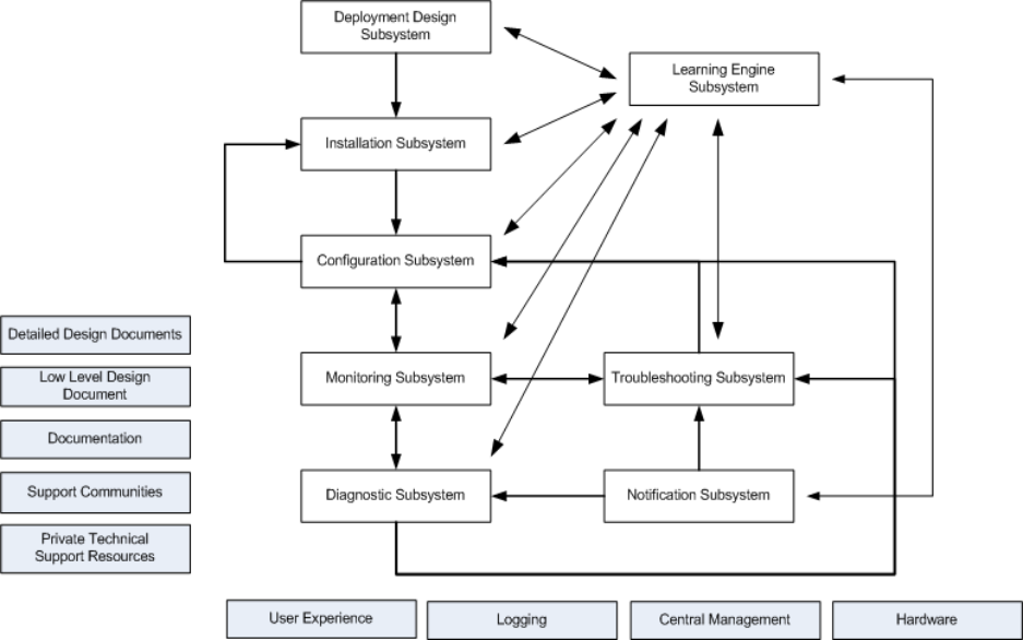
The serviceability architecture is composed of eight subsystems that work together to provide the facilities to design, deploy, and operate a service/system (see Figure. 2). The term subsystem is used to identify the different architecture components in order to differentiate one class of functionality from another and is not intended to represent the architecture necessary to implement a serviceability solution. While the architecture is represented using structures common to software develop design process we do not intend to suggest that this is strictly a software model and a typical service deployment will be a hybrid of humans and systems providing the functions.
Guiding Principles There are a number of concepts that are less architectural and serve more as principles that should be considered when addressing the serviceability concerns of a service/system. They are included separately from the subsystems in order to establish a mindset that is applicable across all of the subsystems.
Figure 2. Serviceability Architecture
Central Management Consolidating the installation, configuration, monitoring, and notification capabilities across the different hardware and software components that make up a service into a single location greatly impacts a customer’s ability to both manage and troubleshoot a service. This principal should not be construed to mean that the hardware and software components should not provide these capabilities themselves, however, that they should provide the ability to be consolidated into a centralized capability. The principal also encompasses associated directives such a utilizing a common set of terms, interaction models, log locations, documentation access, etc.
User Experience Providing a common, consistent customer user experience is important to a serviceable service/system. The application of generally accepted design principles will dramatically improve the overall efficacy and utility of a service. Such principals include the use of an object-action interaction model, progressive disclosure, common vocabulary, task-oriented flows, etc.
Documentation The traditional methods employed in constructing, delivering, and accessing documentation do not transfer well to the delivery of services and systems in the age of distributed, multi-component solutions that are aggregates of multiple vendor products. Documentation should be task-oriented (installation, configuration, troubleshooting), accessible via the system, support tagging (with a common set of tags), and be modular to support ease of use.
Logging The content, structure, and location of system log files for the components of a service system should be common. Users should not require a decoder ring to decipher the contents of log files and all acronyms, error codes, etc. should be accessible from within the context of the log files, either through co-location or through the user of a log file viewer.
Application Programmable Interface (API)
Providing alternative access to system component operations (non-GUI or CLI based) is important for supporting centralized management and integration with existing centralized management systems. It is recommended that all subsystem components provide access to common actions and relevant monitoring data through an application programmable interface.
Hardware Security The ability to configure and manage the hardware components of service/system should not be overlooked. Proving basic hardware health and status monitoring, remote management, easy installation and replacement, etc. impact the overall serviceability of system and the services running on it.
Support Communities Utilizing community-based support communities benefits both the customer and service vendor. These communities can benefit from the knowledge and experiences of service customers as well as provide streamline facilities for delivering content to customers.
Deployment Design Subsystem The deployment design subsystem encompasses the processes associated with identifying the business problem the customer is trying to address, the environment in which the solution to the problem will be implemented, and an implementation plan that includes the hardware and software that makes up the solution and how to deploy them. Properly capturing the relevant customer information in the form of features, performance expectations, capacity requirements (present and future) and information about the customer’s network, storage, and compute environment and the locations where the solution will be deployed and having this information available to the original and future solution designers as well as to other serviceability subsystems will enable more robust solutions and feedback to customers and support personnel when a service/system approaches or exceeds their original values.
The deployment design subsystem is composed of the following components: Requirements Collection, Functional Analysis, Implementation Plan, and Reference Architectures. There are a number of concepts that are less architectural and serve more as principles that should be considered when addressing the serviceability concerns of a service/system. They are included separately from the subsystems in order to establish a mindset that is applicable across all of the subsystems.
Requirements Collection The requirements collection component embodies the identification and collection of information from a customer that directly impacts the final system deployment design. This information can be classified into four categories: features, performance, capacity, and deployment environment.
Features – a distinguishing characteristic of a system, one that the system is purported to provide and something that a customer would be interested in applying to a business problem they are trying to solve.
Performance – measure or perception of how well a system is able to successfully complete the operations that it was designed for. Performance can be measured objectively in terms of speed of completing a single operation, the average of multiple like operations, etc. or subjectively such as a user reporting the system is operating slowly.
Capacity – the number of things (e.g., network packets, call center agents, virtual machines) that a system can support while performing at the expected level.
Deployment Environment – a characterization of the customer’s environment (network, storage, and compute) that is the target into which the system will be deployed.
Functional Analysis The functional analysis complement utilizes the data captured from the requirements collection component to determine the different elements and their number that should be included in the implementation plan. Product features, system performance by capacity data and heuristics are used to in the analysis process. As with requirements collection the knowledge and experience of the person performing the functional analysis has a direct impact on the outcome of the analysis and utilizing tools that embed the analysis logic will improve the accuracy of the results of this process.
Implementation Plan The implementation plan component is responsible for constructing the design of the system to meet the needs of the customer taking into account the outcome of the functional analysis as well as the customers exiting environment. Referred to as a detailed design and low level design by Cisco Advanced services the resulting plan would include specific configuration information or guidelines that match the new hardware/software with the customer’s existing network, storage, and compute environment.
Reference Architectures Reference architectures provide a template solution for implementation of an architecture particular to one or more capabilities (e.g. unified communication, IP network, server virtualization) that are based on generalization from a number of prior deployments. The reference architecture provides a common set of components, connectivity, and terminology with which to describe the deployment. A set of capabilities (solution) could have multiple reference architectures that share common components but differ in terms type of component providing the same capability to address capacity.
Installation Subsystems The installation subsystem addresses the serviceability issues that begin with the customer receiving system product(s), covers the unpacking, racking, and cabling hardware that is part of the system and ends with the installation of the base software/firmware required to enable the product(s) for configuration.
Pre-Install Validation The pre-installation validation component addresses the activities that occur when a customer or customer representative receives the products that have been ordered in support of the deployment plan. Standard operating procedures dictate that the customer must verify that they have received all of the items that were purchased. In order to efficiently accomplish the verification process the customer must compare a list of ordered items against the set of items received; historically this has been a manual process, however increasingly technology is replacing the manual operations utilizing handheld scanners, bar codes, electronic purchase orders, and inventory management systems.
Assemble/Racking/Cabling The assembly, racking, and cabling of systems can result in a number of problems resulting in calls for support for instruction, replacement components, cables, etc. This component addresses the need for proper user instructions, labeling, packaging, component placement, cabling and cabling systems, and the racking of components.
Component/Device Discovery The component/device discovery component addresses two types of discovery: 1) the self-discovery that a component/device performs that detects the presence of add-in modules, blades, cards, memory, etc. and 2) the discovery of components/devices by a centralized management system.
Software Installation The Software Installation component addresses the installation of the base server operating system or firmware on the device. The base installation is intended to prepare the component/device for configuration as a standalone entity or as part of a larger system. The component is also used to add applications, drivers, and to update the software/firmware on servers and devices that have already been installed. The component provides an infrastructure to collect responses from users, files or other components in response to input demands by the software being installed, these inputs can be validated against the rules contained within the validation engine at different times during the installation process. Techniques and technologies included within this component are: attended installation, silent installation, unattended installation, self-installation, headless installation, network installation and virtual installation.
Upgrade Engine The upgrade engine component provides the logic that supports the installation of new versions, drivers, and patches to servers and devices. The logic contained in the upgrade engine focuses on determining the compatibility issues associated with modifying an existing installation with new software as well as understanding the dependencies and update ordering issues among the different components in a system. The upgrade engine can direct and orchestrate the upgrade process automatically through interfacing with the installation component or can guide the user through the upgrade.
Validation Engine The validation engine component evaluates the inputs provided by a user or other components against a set of rules and heuristics. See Error: Reference source not found below.
Configuration Subsystems The configuration subsystem focuses on the initial configuration and subsequent post deployment configuration changes. The subsystem makes use of the shared validation engine during the configuration process as well introduces addition components to track system changes, archive configurations to support recovery, and managing licenses.
Device Discovery The device discovery component is similar to the discovery component employed by the installation subsystem but is mainly focused on the discovery of new devices added to a deployed service. This component monitors the environment and recognizes changes related to the presences of new devices and passes that information to the configuration component in order to make it available for configuration. This component is responsible for walling off the newly discovered device from impacting the health of the service/system until such time as it is properly configured.
Configuration The configuration component manages the make-up of the devices, operating systems, applications, and solutions that combined constitute the service/system. The configuration process is simply the set of steps and the information needed by the target element to properly configure it in order for it to perform its intended function. Interdependences among and between components are managed within the process which utilizes information contained with the validation to manages the configuration flow.
Archive Archiving this history of changes made to the configuration of a service/system is managed by the archive component. This component manages the information stored, where it is stored, how often/when it is stored, and provides methods to restore stored configurations.
Change Management The archive component manages storing system configuration the change management component captures and stores the changes made to the service/system configuration. The change management component captures the change made, who made the change, and when the change was made. In addition this component provides the ability for a user or system to view this information. The component may also provide the ability to export and replay a set of changes made on a different system in support of problem troubleshooting.
License Management The license management component provides the capabilities to identify, delegate, and manage the licenses with the deployment of a service/system. In addition, the component can provide reporting capabilities along with notifications of pending license expirations.
Validation Engine The validation engine component evaluates the inputs provided by a user or other components against a set of rules and heuristics. See Validation Engine below.
Difference Between Troubleshooting and Diagnosis The difference between troubleshooting and diagnosis is not distinct or easily distinguishable. For the purposes of the serviceability architecture, troubleshooting is defined as a “hands-on” activity which may entail the disassembly of a system, hardware and software, to help identify defective components, requires the use of measurement and test tools that are not part of the system, and will result in system downtime and higher cost. Diagnostics are performed remotely, using information that can readily be obtained from the system and involves the analysis of discrete information and trends, and is facilitated by the understanding of the relationships between the system components and the performance of the system.
Diagnostic Subsystem The diagnostic subsystem is responsible for determining whether a system is operating normally or whether it appears to be approaching a condition where it may fail to operate normally. When such a situation is suspected the subsystem attempts to identify the cause of abnormal or unexpected behaviors, to mitigate problems, and to provide solutions to system operations issues. The methods used to perform these functions require the orchestration of information obtained from the monitoring, notification, configuration and troubleshooting subsystems. This information is applied to system operation models in the form of algorithms, heuristics and techniques in order to determine whether the behavior of the system is correct. When a system is found to be functioning incorrectly the same or additional logic is used to determine which part of the system is behaving abnormally and the type of fault that is suspected of causing the problem. Advanced diagnostic systems, in conjunction with the troubleshooting subsystem, provide the ability to perform automatic corrective action once the cause has been accurately identified. The corrective actions may include instructions to change system configurations, advice/direction to administrators, reverting system changes, etc. The subsystem can encompass diagnostic procedures that are manual, interactive, and autonomous.
Reactive Diagnostics The reactive diagnostics component is responsible for monitoring and responding to events and alarms generated by the notification subsystem and directly inspect the (sensor) data captured by the monitoring subsystem with the goal of reacting to abnormal or unexpected system behaviors. The reactive diagnostics component must be configured with fault frames. A fault frame is an information structure that identifies conditions representative of "stereotyped situations." In the case of system diagnostics a fault frame represents the set of events and data that correspond to specific conditions within the system that are associated with abnormal behaviors and failures. A fault frame may include the ability to seek out additional data that is not readily available from the monitoring subsystem (such as configuration data) or algorithms (scripts) that can be executed to test for specific conditions or acquired sensor data that is not captured as part of routine monitoring in support of identifying the source of the problem. A fully defined fault frame would include remediation required to address the identified fault. When the conditions of a fault frame have been met the reactive diagnostic component will send a message to the Orchestrator component notifying it of the fault and providing the remediation information contained the fault frame.
Predictive Diagnostics The predictive diagnostics component operates similarly to the reactive diagnostics component with the primary exception being that with predictive diagnostics the fault frames are defined to predict system abnormal behavior and to make system corrections to prevent the problem from occurring. Operational models are developed using historical data used to identify the system events and monitor values that are correlated with abnormal system behaviors. Through repeated observations of the relationship between data measurements and system performance the suspected cause and effect relationships can be formed into predictive models. The relationship between monitored values and how the system performs can be modeled in a fault frame, but unlike a reactive diagnostic fault frame, the predictive fault frame will look to match events and sensor data that may not have an obvious relationship to the problem it is trying to prevent. In addition the remediation that might be included in the fault frame may not be targeted at services associated with the problem.
Orchestrator The orchestrator is responsible for managing communication across the different SAF subsystem; see the Orchestrator section in the Shared Architectural Components for more information.
Self-Healing Engine The self-healing engine component is responsible for taking instruction from the orchestrator (provided by other subsystems) and implementing those changes; see the Self-Healing section in the Shared Architectural Components for more information.
Scheduler The scheduler component is responsible for managing the execution of scheduled activities across the different SAF subsystem; see the Scheduler section in the Shared Architectural Components for more information.
Troubleshooting Subsystem The troubleshooting subsystem is responsible for supporting the logical, systematic search for the source of a problem so that it can be fixed and the system made operational. Troubleshooting processes are critical to maintaining systems where symptoms of a problem can have many possible sources. Troubleshooting requires the identification of system malfunctions through the use of monitoring data, events, and alarms. Troubleshooting is most often a process of elimination, potential causes of problems are identified and potential causes are discounted or confirmed. Confirmation that a problem was the cause of a malfunction typically comes in the form of restoration of the system to a normal working state.
A system can be described in terms of its expected, desired or intended behavior, its ability to provide a set of services based on the availability of resources and proper configuration. A model of how the system should operate under normal, proper condition is essential in order to be able to identify when it is not performing as it should, events and inputs to the system are expected to generate specific results or outputs. When a problem occurs, it can be described in terms of symptoms of a malfunction (a deviation from expected behavior) and troubleshooting is the process of isolating the specific cause or causes of the symptom. Efficient troubleshooting requires a clear understanding of expected behavior and the relationship between the symptoms of a problem and the set of prospective causes that could lead to the symptoms. The progressive elimination of the possible causes until the root cause is found characterizes the troubleshooting process.
Typically the troubleshooting process ends when the problem is resolved. This is due to the nature of the processes needed to eliminate possible causes, in order to test whether a specific condition has caused the malfunction the suspected problem has to be remedied and then the system monitored to see if it returns to a normal working state. Depending on the state of the system this process can lead to spurious changes to the system that do not fix the problem and could lead to additional problems. Backing out changes that do not address the problem being investigated is important to ensuring that the changes made during the troubleshooting process that did not fix the problem are reverted in order to avoid unexpected consequences.
Troubleshooting is the process of finding and eliminating the cause of a problem. The process is an iterative one that can be characterize by the steps below:
1) Monitoring information is collected and analyzed by system or user, 2) A failure or performance anomaly is identified, 3) Possible causes of the problem are identified, 4) One of the possible causes of the problem is selected and a fix for the problem is implemented,
5) The system is monitored to determine if the fix has resolved the problem. If the system returns to normal state the problem is determined to be fixed, if not then another possible cause for the problem is selected and the fix for that cause is implemented. This process is repeated until the system returns to normal state.
The efficiency of the troubleshooting process is a function of a number of factors ranging from the fidelity and accuracy of the errors reported by a system when an error is identified to the expertise of the user or system involved in the identification of possible causes of the problem.
Troubleshooting Methods There are a number of troubleshooting methods that may be supported within a troubleshooting subsystem and those included will impact how the system reacts to and solves problems. Examples of troubleshooting methods to consider are 1) frequency of incidence, 2) system bisection, 3) flow charts, 4) checklists, 5) procedures, and 6) root cause analysis.
Fault Identification The fault identification component is responsible for identifying when faults occur in a system. The component is configured to look for events that are indicative of a problem in the system. The fault identification registers with the notification subsystem to be notified when specific events occur within the system; the set of fault cases that are registered with the troubleshooting subsystem identify the events that are registered. When the fault identification component is notified that a fault event took place the component will identify the fault cases that have this event defined as a condition of presence and send those fault cases to the orchestrator for disposition of the fault case.
A fault case can have multiple events that need to be present in order for the fault to be considered to have occurred. The fault identification component needs to contain logic in order to coalesce the presence of the events, manage the temporal relationships among the different events within a fault and to clear faults from consideration based on expiration periods and other dependencies (such as a reboot, etc).
Cause Isolation The cause isolation component is responsible for paring the set of fault cases that have been identified as possible causes of a fault. This component possess the logic to analyze the properties of the set of fault cases passed to it by the orchestrator component and to identify attributes and their values that distinguishes them from each other. The distinguishing attribute values can then be collected, using the symptom collection component, and the results can then be used to eliminate fault cases from the set of possible fault cases when they do not match the expected values.
Symptom Collector The symptom collector component collects monitoring and configuration information from system components in response to requests made to it by the cause isolation component. The symptom collector is configured to be able to access monitoring and configuration information from the different components that make up the system. It must be able to support the different industry standards for remote access and must be able to support changes to the configuration without disrupting current processes. The system must allow remote access to configuration information and so this information needs to be in a machine readable format that does not require heroic effort to access.
Orchestrator The orchestrator is responsible for managing communication across the different SAF subsystem; see the Orchestrator section in the Shared Architectural Components for more information.
Self-Healing Engine The self-healing engine component of the troubleshooting subsystem is responsible for taking problem remediation instructions from the orchestrator and implementing those changes. The instructions usually take the form of modifying system component configuration values but can include sending instructions to the user via an application user interface or resetting a device. The self-healing engine contains a library of command sets that are associated with a system component and commands that can be used to manipulate that component, through a supported interface such as an API (application programmable interface), a user interface (CLI or GUI), SNMP, etc. The system component would provide support for the interface and the self-healing engine would construct the set and execution order of configuration and management programs to utilize those interfaces.
Solution Verification The solution verification component is responsible for verifying that the system has returned to normal or expected operation when instructed to do so by the orchestrator, the post-corrective state is defined within the normal operations model for the system or within the fault case if the solution will put the system in a non-optimal/normal state. The orchestrator will provide the set of “tests” that the solution verification component is to perform to make the determination, which will usually involve operations such as determining the status by comparing monitored values with normal system operation values, and looking for specific events/messages in component log files. The outcome of the execution of each test is returned to the orchestrator in order for the orchestrator to capture and report them to the notification subsystem.
Notification Subsystem The notification subsystem is responsible for passing along the alerts and events identified by the monitoring subsystem to the appropriate subsystems, user interface or API. The notification subsystem is composed of a configuration, engine, and delivery component.
Notification Configuration The notification configuration component is used to identify the alerts and events that should be passed along, the components they should be passed along to, the protocol to be used, and the method to be used to verify delivery.
Notification Engine The notification engine component uses the configuration information defined in the notification configuration component and the messages received from the monitoring subsystems and determines what notifications should be sent to where.
Notification Delivery The notification delivery component performs the mechanics of connecting to a notification target, transferring the message, enduring delivery, and verifying the receipt.
Learning Engine Subsystem The learning engine subsystem represents the higher level cognitive functions performed by humans such as reasoning, generating and verifying hypotheses, pattern recognition, etc. These capabilities are found in various forms in different industries and while applicable to the SAF they have not been adequately evaluated for inclusion.
Shared Architectural Components Chapter contains the discussion of components that can be found in multiple subsystems and may be implemented as a single component shared across subsystems.
Scheduler The scheduler component is used to manage the execution of operations that have be configured to occur on a define frequency. A schedule item will identify the activity to be executed, the frequency of execution, time of day to be run, and the maximum time to run. The scheduler supports the ability to monitor the execution of scheduled activity and to terminate an activity should it not be completed by the maximum time to run. The scheduler should prevent two of the same activities from executing at the same time. The engine will report to the orchestrator the successful completion or failure to complete the set of instructions provided.
Orchestrator The orchestrator is responsible for managing the communication and interplay between SAF subsystems. Messages are passed between subsystems through the orchestrator which is configured to control how it responds to these inputs. The orchestrator is configured with order and dependency rules in order to properly order message passing and to manage communication.
Validation Engine The validation engine evaluates the inputs provided by a user or other components against a set of rules and heuristics. The engine provides or establishes simple field level validation (such as regular expressions), field-to- field validation (if value X then user must provide value Y), object/page validation (all data provided for object Z), and solution level validation (all required components have been properly configured). A common validation engine underscores the importance of a common set of logic and infrastructure to validate installation of individual components and their interdependencies.
Self-Healing Engine The self-healing engine is responsible for taking instruction from the orchestrator (provided by other subsystems) and implementing those changes. The instructions take the form of modifying system component configuration values but can include sending instructions to the user via an application user interface or resetting a device. The self-healing engine contains a library of command sets that are associated with a system component and commands that can be used to manipulate that component, through a supported interface such as an API (application programmable interface), a user interface (CLI or GUI), SNMP, etc.
CONCLUSIONS
This paper introduced a serviceability architecture that can be used to describe a common process model for deploying service solutions and identified the serviceability capabilities that should be considered. A vocabulary for describing the architecture and its components is introduced. This model can be used in evaluating the serviceability capabilities provided by solutions as well as in the development of those solutions. There have been a couple of efforts within Cisco to apply the serviceability architecture in the development of a taxonomy for an internal support community (Allen, 2013) and the evaluation of customer focused content for smart services products.
REFERENCES
Allen, D.M., Schneider, T. (2013), “The Role of the Community in a Technical Support Community: A Case Study”, in OCSC/HCII 2013, Ozak, A. and Zaphirirs, P. (Eds). pp. 335-244.
LISTED IN THE AHFE DIGITAL BOOKSTORE CATALOGUE
Explore the complete digital volume
Advances in The Human Side of Service Engineering
Read this individual research paper free through the original publisher, or explore the full digital proceedings book.
ISBN 978-1-4951-2091-6
Explore this ISBN in the AHFE Bookstore ↗Listed in the July 2026 bookstore catalogue; search by ISBN to confirm current availability · Digital book purchase optional