Chengming Gao, Dahai Zhang (2024). Reduction and Modification for Aero Engine Rotor Model Considering Contact Stiffness. In: Advances in Human Factors of Transportation. AHFE Open Access, vol. 148, pp. 95–104. https://doi.org/10.54941/ahfe1005199
Aiming at the difficulty of both accuracy and computational efficiency in aero engine rotor model, a method of dimensionality reduction and modification of aero engine rotor model considering contact stiffness is proposed. First, a three-dimensional finite element model of the aero-engine rotor is established, using thin-layer elements to represent the end-tooth contact interface between rotor discs. Second, based on the Craig-Bampton fixed-interface modal synthesis method, a reduced model of the rotor is obtained, retaining the main nodes at the bearing and the end-tooth contact interface positions. Finally, the contact stiffness in the reduced rotor model is modified based on the sensitivity method and rotor modal testing. The maximum frequency error of the first three orders of bending mode frequencies calculated by the modified model is reduced from 12.84% to 0.11%, and the calculated modal shapes are consistent with the experimental results. Moreover, the average time of five iterations of correction calculation is 0.8 seconds on the platform of Matlab software, which verifies the accuracy and efficiency of the method. The calculation results show that the dimensionality reduction and modification method considering contact stiffness can not only satisfy the correction accuracy, but also significantly improve the model correction efficiency of aero engine rotor.
Modern aero-engines are continuously developing towards higher thrust-to- weight ratios and higher speeds, making accurate modeling of aero-engine rotors increasingly important.
In recent years, the modeling of rotor-contact interface characteristics has become a focal point in dynamics research. Model correction for aero engine rotors through the adjustment of contact interface parameters is a key development in this area. Jalali simulated contact surface stiffness and damping characteristics using thin-layer elements (Jalali et al., 2011). Zhao characterized contact interfaces using thin-layer elements and analyzed the relationship between contact stiffness and bolt preload (Zhao et al., 2018). Jiang performed finite element modeling of bolted joint structures based on
thin-layer element theory and identified parameters for the thin-layer ele- ments (Jiang et al., 2014). Liu explored the relationship between thin-layer element parameters and the stiffness of bolted joint structures in aero engines (Liu et al., 2018). Miao employed thin-layer elements to simulate the contact relationships in rotor components (Miao et al., 2019).
However, due to the complex structure of aero engine rotors, iterative model correction using solid finite element models involves massive calcula- tions and low efficiency. Therefore, dimensional reduction techniques can be applied to reduce computational load and enhance computational efficiency. Dimensional reduction is a technique that transforms high-dimensional data into a lower-dimensional representation, significantly reducing computa- tional complexity. Wagner conducted a survey and overview of model reduc- tion methods, with modal synthesis being a widely applied technique in rotor dynamics engineering applications for aero engines (Wagner et al., 2011). Wang used the free-interface modal synthesis method to conduct vibration analysis on three-dimensional rotors (Wang et al., 2015). Zheng combined fixed-interface and free-interface modal synthesis methods for steady-state response calculations on rotors (Zheng et al., 2019). Sun combined the fixed-interface modal synthesis method to propose a dimensional reduction technique suitable for complex structures, this method takes load-affected and support areas as reserved substructures, obtaining reduced mass matri- ces, stiffness matrices, and gyroscopic matrices (Sun et al., 2017). It has been successfully applied in the dynamic response analysis of aero engines.
Existing literature shows that although thin-layer elements can effectively simulate contact interface characteristics, there is a need for repeated calls to the simulation finite element model in the iterative process of modifying thin-layer parameters. When multiple parameters are modified for optimiza- tion, this leads to high computational loads and low modification efficiency. Therefore, this paper takes the gas generator rotor as the research object, characterizes the end tooth contact interface between the rotor discs by thin- layer elements, then retains the end tooth contact interface as the main node, reduces dimension through the fixed interface modal synthesis method, and then modifies the stiffness of the main node. The method proposed in this paper is simple to apply and convenient for calculations, ensuring good modification precision and significantly improving the efficiency of model modifications, proving highly practical for engineering applications.
THEORY OF DIMENSIONAL REDUCTION AND MODEL MODIFICATION CONSIDERING CONTACT STIFFNESS In this paper, the Craig-Bampton fixed-interface modal synthesis method is applied to reduce the dimensions of a solid aero-engine rotor model (Sun et al., 2017). The vibration differential equation of the rotor system can be described as:
Md ¨ud +
Cd −ωGd
˙ud + Kdud = Fd (1) Where Md, Cd, Gd and Kd are the mass matrix, damping matrix, gyro- scopic matrix, and stiffness matrix of the rotor system, respectively; w is the rotational speed, ud is the displacement, and Fd is the load.
Reduction and Modification for Aero Engine Rotor Model Considering Contact Stiffness 97
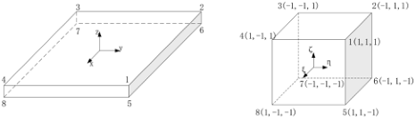
Before reduction using the modal synthesis method, thin-layer elements are established between the rotor end teeth to represent the end-tooth con- tact interface between the rotor discs. When reducing the dimensions, it is necessary to select the load application positions and the bearing positions as the master nodes, while the other nodes are treated as slave nodes. Generally, in the rotor system, the positions where the centrifugal force is applied are the centroids of each wheel disc, the positions where the contact force is applied are the end surfaces of the contacts, and the bearing force is applied at the center of the rotor shaft. In this paper, the centers of the rotor shaft neck, the centrifugal impeller, the gas turbine disc, and the centers of the contact surfaces on both sides of the thin-layer elements are selected as master nodes. Assuming the dimensions of the thin-layer elements are l×d×t, the thin-layer element stiffness matrix is calculated using an isoparametric transformation (see Figure 1):
Z 1
Z 1
Z 1
Z d
Z t
Z l
BTDB det(J)dξdηdζ (2)
Equations and mathematical formulas are available in the original paper PDF.
Where D is the elastic matrix of the thin-layer material, B is the geometric matrix of the element, and J is the Jacobian matrix of the element.
Figure 1: Isoparametric transformation of thin-layer element.
By combining the stiffness matrix of the thin-layer element with the ele- ment stiffness matrix of the rotor components, we form the whole structure stiffness matrix, resulting in the vibration differential equation of the rotor:
˙um ×
−ω
˙us
¨um ¨us
Cm Cms Csm Cs
Mm Mms Msm Ms
Gm Gms Gsm Gs
Km Kms Ksm Ks
us
(3) Where Mm, Cm, Gm, Km represent the mass, damping, gyroscopic, and stiffness matrices described by the master node degrees of free- dom; Ms, Cs, Gs, Ks represent the mass, damping, gyroscopic, and stiffness matrices described by the slave node degrees of freedom; Mms, Msm, Cms, Csm, Gms, Gsm, Kms, Ksm represent the coupling mass, damp- ing, gyroscopic, and stiffness matrices described by master and slave node degrees of freedom; um and us represent the displacement vectors for mas- ter and slave nodes; Fm is the load vector corresponding to the master node degrees of freedom.
98 Chengming and Dahai
Viewing the system as composed of constraint interface retained master modes and all interface degrees of freedom of constraint modes, we get:
Im 0 −K−1
um qbl
s Ksm 8bl
Where ud is the displacement vector; Im is an m-dimensional identity matrix; 8b are the retained master modes; qbl are the modal coordinates correspond- ing to the retained master modes; 8d is the assumed mode matrix; qd are the generalized modal coordinates corresponding to the assumed mode matrix.
Substituting (4) into (1), we obtain the motion equation described by the generalized modal coordinate qd :
Where:
d Cd8d
d Fm Equation (5) is the reduced dynamic equation of the rotor, which contains m-dimensional master node degrees of freedom and l-dimensional retained mode degrees of freedom, greatly reducing the computational dimensions of the original model.
Consider the influence of the contact between the rotor discs, and select the contact stiffness of the thin-layer elements at the contact interface for correction. When reducing the model dimensions, the centers of the contact surfaces on both sides of the thin-layer elements are set as the main nodes, and the stiffness of each main node at the thin-layer elements is corrected. Taking the correction of a set of contact stiffness of the thin-layer elements as an example, the reduction stiffness matrix during correction is as follows: [Equation or mathematical symbol available in the original paper PDF][Equation or mathematical symbol available in the original paper PDF]
k11
kmm + 1k
knn + 1k
Equations and mathematical formulas are available in the original paper PDF.
[Equation or mathematical symbol available in the original paper PDF] kzz Where kmm, knn represent the stiffness of the main nodes on both sides of the thinlayer elements, and 1k represents the additional stiffness value at the main nodes during correction.
The problem of finite element model correction can be seen as an optimization problem, where the error between the modal frequencies from the finite element analysis and the experimental modal frequencies forms the objective function for model correction:
fa,i −fe,i
n X
Where fa,i and fe,i represent the ith-order finite element analysis modal frequency and experimental modal frequency of the model. In this paper, a sensitivity-based correction method is used to correct the model.
Reduction and Modification for Aero Engine Rotor Model Considering Contact Stiffness 99
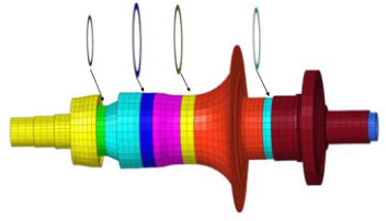
GAS GENERATOR ROTOR MODEL DIMENSION REDUCTION The gas generator rotor is configured as a central tie rod rotor, consisting of compressor discs, centrifugal impellers, gas turbine discs, and a central tie rod, among other components. The rotor model retains the actual char- acteristics of an aviation engine rotor. To facilitate rotational testing and to simplify manufacturing, blades on each of the rotor’s discs have been omitted from the model. The high-dimensional solid element model of the gas gen- erator rotor was established using HyperMesh software (see Figure 2). The original end-tooth structure between the discs was replaced with an equiva- lent simplified geometric feature, the equivalent annulus (Yang et al., 2020). At the interface of the equivalent annulus, thin-layer elements represent the contact stiffness of the interface; the model has 10980 elements and 99180 degrees of freedom.
Figure 2: Gas generator rotor model with thin-layer element.
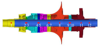
Principal nodes were established at the centers of the two end shaft necks, the centroids of the centrifugal impeller and the gas turbine discs, and the cen- ters of the contact surfaces on both sides of the four thin-layer elements. These principal nodes are connected to their corresponding solid element regions through mass-less beams, being designated as reserved nodes (see Figure 3). Nodes 1 and 12 represent the shaft neck reserved nodes, and nodes 8 and 11 are reserved for the centrifugal impeller and the gas turbine disc, respec- tively. Nodes 2 and 3, 4 and 5, 6 and 7, and 9 and 10 correspond to the reserved nodes on both sides of the four thin-layer elements and are the prin- cipal nodes to be corrected. The reduced mass matrix, stiffness matrix, and gyroscopic matrix of the rotor were obtained by ANSYS analysis. The num- ber of reserved modal orders was set to 20. Given the characteristics of the solid elements, each reserved node had three translational degrees of freedom in the x, y, and z directions, resulting in a reduced structure with a total of 56 degrees of freedom. Using the ANSYS finite element analysis software and Matlab software to calculate modal frequencies through the reduced matrices, a comparison of the first three-order bending mode frequencies is shown (see Table 1). The results indicate that the dimensionally reduced model of the gas generator rotor established using the methods described in this paper is consistent with the modal frequencies of the three-dimensional solid finite element model,
100 Chengming and Dahai
confirming the accuracy of the dimensionality reduction method applied to modal analysis.
Figure 3: Reserved nodes for the dimensionality reduction model of gas generator rotor.Table 1. Comparison of modal frequencies of rotor models before and after dimension reduction.
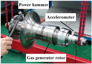
MODAL TESTING OF GAS GENERATOR ROTOR In order to obtain an accurate dimensionally reduced model of the gas gener- ator rotor, modal testing of the gas generator rotor was carried out to acquire modal data for comparison and correction against computational results of the reduced model. To ensure accuracy in test outcomes, a free-hanging instal- lation approach was chosen wherein the gas generator rotor was suspended using elastic cords to simulate “free-free”boundary conditions. A multi-point excitation and single-point response hammer test method was used for the free modal testing (see Figure 4). The modal analysis yielded the first three bending mode frequencies and shapes of the gas generator rotor.
Figure 4: Modal test of gas generator rotor.
Reduction and Modification for Aero Engine Rotor Model Considering Contact Stiffness 101
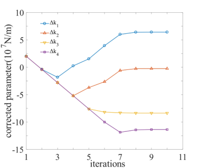
GAS GENERATOR ROTOR MODEL MODIFICATION The additional stiffness values for the master nodes on both sides of the four thinlayer elements were initially set at 1kj(i = 1, 2, 3, 4) = 2 × 10⁷ N/m. The frequencies of the first three bending modes obtained from the experi- ments were used as the characteristic residual values for modal correction. The trends of changes in the additional stiffness values of the four groups of thin-layer contact stiffness with iteration number are illustrated (see Fig- ure 5). As evidenced from the graph, the additional stiffness values differed among the four groups but each converged rapidly. The convergence results of the correction parameters is presented, with 1k4 showing the great- est variation, indicating that the contact stiffness of this interface exerts the most significant combined impact on the bending mode frequencies (see Table 2).
A comparison for the first three bending modal frequencies of the gas gen- erator rotor before and after correction using the reduced model is listed (see Table 3). Prior to correction, the largest error in modal frequency for the first three bending modes of the gas generator rotor was 12.84%, with an aver- age error of 5.64%. Post-correction, the first three bending modal frequencies were almost consistent with the modal test outcomes. The comparison of the first three bending modes of the gas generator rotor calculated by the mod- ified model and the test is shown (see Table 4). The results indicate that the modal shapes calculated from the dimension-reduced model established by our method are in close agreement with the experimental ones. Upon uti- lizing the Matlab software platform for the tests, the average computation duration was determined through five iterations. The iterative correction process for the contact stiffness at the interface between the gas generator rotor end teeth took 0.8 seconds. This indicates that the method proposed in this article can precisely correct the contact stiffness of the gas gener- ator’s rotor end teeth interface, significantly enhancing the computational efficiency.
Figure 5: Iterative convergence curve of gas generator rotor corrected parameter.
102 Chengming and Dahai
Table 2. Comparison of stiffness added value of gas generator rotor before and after correction.
Table 4. Comparison of vibration modes between gas generator rotor test and modi- fied model.
Table available in the original PDF paper.
Simulation mode shape
Modal order
2D experimental mode shape
3D experimental mode shape
CONCLUSION
Based on the research conducted, the following conclusions were drawn: (1) The contact interface between rotor components is characterized by thin-layer elements, and the contact stiffness of the rotor model is mod- ified by selecting the two sides of thin-layer elements as the main nodes for dimensionality reduction. This achieves a dimension reduction and
Reduction and Modification for Aero Engine Rotor Model Considering Contact Stiffness 103
correction method for aero engine rotor models that considers contact stiffness. (2) Following model corrections based on sensitivity analysis, the calculated bending mode frequencies and mode shapes of the reduced rotor model exhibit a high degree of conformity with experimental results, and the computational efficiency is notably enhanced. (3) The rotor model correction method for aero engines proposed in this study explores new avenues for accurately constructing aero engine rotor models. It realizes an effective balance between model precision and computational efficiency and holds significant theoretical and practical application value. It provides new reference standards and application demonstrations for the correction and optimization of aero engine rotor models.
ACKNOWLEDGMENT
The research work is supported by the National Natural Science Foundation of China (52005100), the National Science Fund for Distinguished Young Scholars (52125209), the Jiangsu Natural Science Fund (BK20231542), the Key R&D Plan of Jiangsu Province (BE2022158), the Jiangsu Association for Science and Technology Young Talents Lifting Project (TJ-2022-043), the Zhishan Youth Scholar Program of SEU (2242021R41169) and the Fundamental Research Funds for the Central Universities.
REFERENCES
Jalali, H. Hedayati, A. Ahmadian, H. (2011). Modelling mechanical interfaces experiencing micro-slip/slap. Inverse Problems in Science and Engineering, 19(6), pp. 751–764. Jiang, D. Wu, S. Q. Shi, Q. F. Fei, Q. G. (2014). Parameter identification of bolted-
joint based on the model with thin-layer elements with isotropic constitutive relationship. Journal of Vibration and Shock, 33(22), pp. 35–40. Jiang, D. Wu, S. Q. Shi, Q. F. Fei, Q. G. (2015). Contact interface parameter identification of bolted joint structure with uncertainty using thin layer element method. Engineering Mechanics, 32(04), pp. 220–227. Liu, Y. Wang, J. J. Chen, L. Q. (2018). Dynamic Characteristics of the Flange Joint
with a Snap in Aero-Engine. International Journal of Acoustics and Vibration, 23(2), pp. 168–174. Miao, H. Zang, C. P. Luo, X. Y. Wang, X. W. Liang, B. (2019). Dynamic modeling and updating for contact interface of rod fastening rotor based on thin-layer element. Journal of Aerospace Power, 34(09), pp. 1927–1935. Sun, C. Z. Chen, Y. S. Hou, L. (2017). Modeling method and reduction of dual-
rotor system with complicated structures. Journal of Aerospace Power, 32(07), pp. 1747–1753. Wagner, M. B. Younan, A. Allaire, P. Cogill, R. (2011). Model Reduction Methods for Rotor Dynamic Analysis: A Survey and Review. International Journal of Rotating Machinery, 2010, pp. 1–17. Wang, S. Wang, Y. Zi, Y. Y. He, Z. J. (2015). A 3D finite element-based model order
reduction method for parametric resonance and whirling analysis of anisotropic rotor-bearing systems. Journal of Sound and Vibration, 359, pp. 116–135.
104 Chengming and Dahai
Yang, Z. L. Wang, A. L. Zhang, H. B. Ma, W. Wang, H. (2020). Study on dynamic characteristics of end-toothed connection rotor considering contact effect. Journal of Mechanical Strength, 42(06), pp. 1489–1495. Zhao, G. Xiong, Z. L. Jin, X. Hou, L. T. Gao, W. D. (2018). Prediction of contact
stiffness in bolted interface with natural frequency experiment and FE analysis. Tribology International, 127, pp. 157–164. Zheng, Z. L. Xie, Y. H. Zhang, D. (2019). Reduced-Order Modeling for Stability and Steady-State Response Analysis of Asymmetric Rotor Using Three-Dimensional Finite Element Model. Journal of Engineering for Gas Turbines and Power, 141(10), p. 141.
LISTED IN THE AHFE DIGITAL BOOKSTORE CATALOGUE
Explore the complete digital volume
Advances in Human Factors of Transportation
Read this individual research paper free through the original publisher, or explore the full digital proceedings book.
ISBN 978-1-964867-24-3
Explore this ISBN in the AHFE Bookstore ↗Listed in the July 2026 bookstore catalogue; search by ISBN to confirm current availability · Digital book purchase optional