To improve the issue of excessive computational complexity in the single-step block precise integration method for nonlinear rotor dynamics calculations, a novel sub-block subdivision approach was introduced to refine Duhamel integration and internal point load estimation through fine-tuned matrix-vector operations. This method effectively sidesteps redundant calculations involving zero and identity matrices by precomputing and storing results corresponding to constant matrices. In preserving the accuracy levels of the conventional algorithm, the refined approach has successfully curtailed the computational workload by approximately 20%. The advanced computational strategy was tested on a dual-disc rotor model to conduct a nonlinear response calculation. The outcomes were benchmarked against results from the established Newmark method, demonstrating efficacy and efficiency of the implemented improvements. Additionally, distinct applicability scenarios of the two algorithms were substantiated.
With escalating demands on the performance of aerospace engines, the role of simulation-based predictive design methods has become increasingly vital (Jianguo, 2018). It is of particular importance to leverage simulation pre- dictions for dynamic response forecasting of aircraft engine rotor systems, which typically involve a multitude of nonlinear elements and numerous degrees of freedom, demanding numerical algorithms with high computa- tional efficiency and accuracy. Owing to the high degrees of freedom and significant nonlinearity in engineering models, challenges persist in the non- linear response computation for rotor dynamics. The Newmark method is hindered by low precision and the necessity for multiple iterations, result- ing in extended computational time, while the Runge-Kutta method often faces convergence issues. The precise integration algorithm, although offer- ing computational accuracy and strong stability for solving homogeneous equations, is problematic when addressing nonlinear issues — dimensional
augmentation (Suying et al., 2003) (Mingxiang et al., 2014) requires longi- tudinal computation of exponential matrices at each time step; Taylor series expansion of load terms (Weidong et al., 2004) (Guangtian et al., 2014) is heavily step-size dependent for accuracy; and current numerical methods for fitting Duhamel integral terms (Suying et al., 2011) (Jie et al., 2020) (Yong et al., 2020) fail to concurrently satisfy high computational precision and efficiency for nonlinear predictions. Moreover, rotor dynamics see limited application of the precise integration method, with a deficit in comparative computational results for rotor case studies.
This paper opts for a single-step block precise integration method with enhanced computational accuracy over similar methods, incorporating it into rotor dynamics calculation. Adaptations are proposed to manage high com- putation demands, involving precomputing sub-blocks in each time step and assembling the results in a simplified manner, and storing constant matrices upfront to augment efficiency. With a dual-disc rotor example featuring a squeeze film damper, this study benchmarks the computational accuracy and efficiency across varying rotational speeds against the Newmark method. The finding furnish an engineering benchmark for employing precise integration methods in simulation-based predictive modelling.
IMPROVED SINGLE STEP BLOCK PRECISE INTEGRATION METHOD The dynamic differential equations of a rotor system can be represented as follows:
M¨x + (C −ωG)˙x + Kx = fu(t) + fn(x,˙x) (1) Here, M,C,G,K represent the system’s mass, damping, gyroscopic, and stiffness matrices of n dimensions, where n is the number of degrees of freedom. is the rotor speed, fu (t) and fn(x, ˙x) represent the linear and non- linear forces acting on the rotor system, and n-dimensional vectors x, ˙x, ¨x correspond to displacement, velocity, and acceleration, respectively.
To address equation (1), transformation matrices are introduced to reduce the second-order differential equation to a set of first-order motion equations within the Hamiltonian framework:
Equations and mathematical formulas are available in the original paper PDF.
0 I −M−1K −M−1(C −wG)
Equations and mathematical formulas are available in the original paper PDF.
Where H is a 2n-dimensional transfer matrix, r is a 2n-dimensional load vector. The solution within an integration time step for equation (2) can be
The first term’s exponential matrix is obtained through a precise calcula- tion method (Wanxie, 1994).
eH1t = (e(H1t/2N))2N = (eHτ)2N (5) The Padé approximation is used instead of the Taylor expansion to improve the accuracy and stability of the algorithm. Here, q = p is taken, where p is the order of expansion; this paper chooses p = 4 and N = 20 (Mengfu, 2006).
The exponential matrix is expanded using the Padé series as follows.
The matrices Ds and Ns are expressed as follows.
(2p−k)!p! (2p)!k!(p−k)!(Hτ)k
Once T0 is calculated, the final result is obtained through the following two formulas.
Ti = 2Ti−1 + Ti−1 · Ti−1(i = 1, 2, ...N) T = I + TN (8) T is thus the desired final exponential matrixeH·1t. For the numerical calculation of the second term, the Duhamel inte- gral term, the literature (Dongbing et al., 2022) applies the Chebyshev- Gauss-Lobato grid on an implicit single-step block method and uses the Runge-Kutta method to predict the internal point loads, with the following computational formula.
9T3r(tk + 3/4,evk + 3/4) + 1 18r(tk + 1,evk + 1) The research work is supported by the National Natural Science Foundation of China (52005100), the National Science Fund for Distinguished Young Scholars (52125209), the Jiangsu Natural Science Fund (BK20231542), the Key R&D Plan of Jiangsu Province (BE2022158), the Jiangsu Association for Science and Technology Young Talents Lifting Project (TJ-2022-043), the Zhishan Youth Scholar Program of SEU (2242021R41169) and the Fundamental Research Funds for the Central Universities.
108 Jiaxuan and Dahai
For each internal point of integration, the expression is as follows:
exk + i/4
e˙xk + i/4 The calculation processT · ris improved as follows:
At the same time, by using the fourth-order explicit Runge-Kutta method, the predicted values of the internal points of integration can be obtained, thus obtaining the corresponding r and rendering the implicit method explicit.
4 × 1 2S2) + r(tk + i1t
4 S3) + r(tk + i1t
Equations and mathematical formulas are available in the original paper PDF.
4 , vk + i1t 4 S3) Improvements to the calculation results ofH · vare as follows:
Equations and mathematical formulas are available in the original paper PDF.
˙x −M−1K · x −M−1C · ˙x
[Equation or mathematical symbol available in the original paper PDF] For steady-state response calculations, sub-blocks of the transfer matrix H can be pre-stored outside of the loop, eliminating the need to compute them in each iteration.
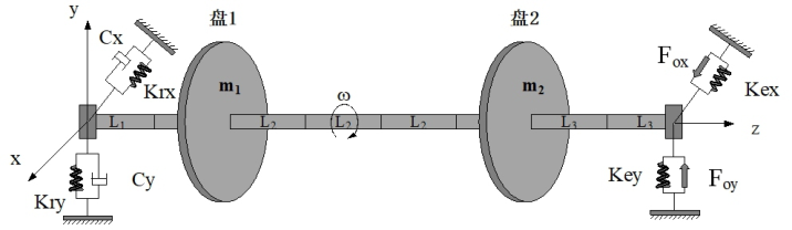
Modelling of the Dual-Disk Rotor System As shown in Figure 1, the rotor system model is established based on the finite element method, discretizing the shaft into 8 segments and 9 nodes (retain- ing the x and y directions’ 4 degrees of freedom at each node) amounting to 36 degrees of freedom. The discs are assumed to be rigid and represented by concentrated mass elements. On the right side of the rotor is a squeeze film damper (SFD) with a squirrel-cage elastic support, represented as in equa- tion (15). A rigid support is used on the left side. Fox, Foy are the oil film
forces in the horizontal and vertical directions, respectively; Fn, Ft are the normal and tangential oil film forces, Kex, Key are the stiffness of the right side’s squirrel-cage elastic support, Krx, Kry, Crx, Cry respectively represent the stiffness and damping (damping taken as zero here) of the left side’s rigid support.
Figure 1: Schematic diagram of rotor-SFD-bearing system.Table 1. Parameter table of rotor structure.
Table available in the original PDF paper.
Parameter Value Shaft section L1/mm 26 Shaft section L2/mm 118 Shaft section L3/mm 69 Shaft diameter D/mm 33 Disk 1 mass m1/t 0.018745 Disk 1 diametral moment of inertia /t·mm2 96.6 Disk 1 polar moment of inertia/t·mm2 188.2 Disk 1 unbalance/t·mm 0.00026 Disk 2 mass m2/t 0.016098 Disk 2 diametral moment of inertia/t·mm2 72.1
Table 2. Parameter table of squeeze film damper.
Table available in the original PDF paper.
Parameter Value Oil film clearance C/mm 0.16 Oil film length L/mm 11 Oil film radius R/mm 67.5 Lubricating oil viscosity µ/mm 2 Static eccentricity ratio ε 0.2
110 Jiaxuan and Dahai
c3 ·
Equations and mathematical formulas are available in the original paper PDF.
c3 ·
Equations and mathematical formulas are available in the original paper PDF.
x2 + y2 (yFn + xFt)
p
Where I1, I2, I3 are Sommerfeld integrals related to parameters like whirling angle, relative eccentricity, er =
(yrotor −yecc)/(xrotor −xecc)
is the journal whirling angle, ˙ψ is the journal’s whirling angular velocity, and (xrotor, yrotor) is the actual journal location, while (xecc, yecc) is the static eccentricity location of the journal, with the structural parameters are shown in the Table 1. And other parameters in the figure as shown in Table 2.
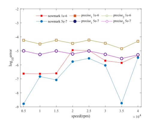
COMPARISON OF COMPUTATION ACCURACY FOR STEADY-STATE RESPONSE OF ROTOR SYSTEM Comparisons of the Newmark method at time steps of 1E-6, 5E-7, 4E-7, 2E-7, and 1E-7 showed that the results of the larger time steps gradually approached those at 1E-7. However, further reducing the time step below 1E- 7 caused a significant accumulation of numerical errors, making the results unreliable. Hence, the Newmark method at 1E-7 time step is considered as the reference for precise values. With the convergence error set to 1E-6 for the Newmark method at different time steps, and with the integration constants and as 0.25 and 0.5 respectively, the error is defined as the mean relative error of the x-direction displacement at disk 1 at several time points after the rotor reaches a steady state when compared to the precise value. By taking various rotational speeds as the horizontal axis coordinates and the logarith- mic values of the relative error as the vertical axis coordinates, an error curve is plotted as shown in Figure 2. Here, ‘precise1’ represents the single-step block precise integration method, while ‘precise2’ represents the improved single-step block precise integration method.
As shown, the improved single-step block precise integration method maintains the same precision as the original algorithm. The relative error shows the following trends: as the rotational speed increases, the accuracy of the same time step Newmark method surpasses the single-step block pre- cise integration, but as the speed increases further, the error of the Newmark method exhibits an increasing trend, while the precision gap between it and the single-step block precise integration generally exhibits a decreasing trend.
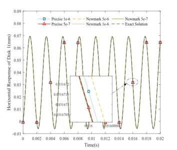
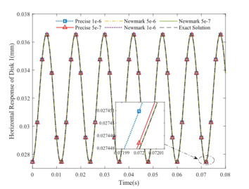
Furthermore, the response results at specific rotational speeds are anal- ysed in Figure 3. Within different rotational speed ranges of the working speed, values at 5000r/min, 25000r/min, and 40000r/min are selected, taking
Figure 2: Relative displacement error at different rotational speeds.
the x-direction response at disk 1 after reaching a steady state as the verti- cal coordinate, and time duration as the horizontal coordinate for plotting (due to the large number of integration points, only a part is shown in the diagram). Still taking the results of the Newmark method with a 1E-7 time step as precise values, because the improved single-step block precise integra- tion method retains the original algorithm’s precision, the results before and after the improvement of the single-step block precise integration method are uniformly presented as ‘Precise.’
(a) (b)
Figure 3: Continued
112 Jiaxuan and Dahai
(c)
Figure 3: Steady-state response curves at different speeds: (a) 5000 r/min (b) 25000 r/min (c) 40000 r/min.
At a speed of 5000 r/min, the computing results of the Newmark method with a step size of 5E-6 are already better than those of the single-step block precise integration with a step size of 5E-7. When the speed is 25000 r/min, the Newmark method with a step size of 5E-6 is relatively the worst in pre- cision; however, with the same step size of 1E-6 and 5E-7, the Newmark method is still closer to the precise results. When the speed reaches 40000 r/min, the results of the Newmark method with a 5E-6 step size further diverge from the exact values, while at the same step size, the Newmark method still has higher precision than the single-step block precise integra- tion. Overall, as speeds increase, the precision of the Newmark method with the same step size is superior to the single-step block precise integration method, but the gap in computational precision between them is gradually narrowing.
It was concluded that the calculation precision of the Newmark method with the same step size is superior to the single-step block precise integra- tion method. The reason is: due to the simplicity of the model and the relatively few degrees of freedom, it is easier to satisfy the computation pre- cision requirements. Although the Newmark method has only second-order precision, it can achieve relatively accurate results with different step sizes through Newton iteration. Although the single-step block precise method has third-order precision, its precision is compromised due to the estima- tion of internal points. Hence, for a simple model with the same step size, the precision of the single-step block precise integration method is inferior to the Newmark method. However, as the model becomes more complex, the number of degrees of freedom increases, and nonlinearity intensifies, the advantages of the higher order of precision of the single-step block precise integration method will become progressively apparent.
COMPARISON OF COMPUTATION EFFICIENCY FOR STEADY-STATE RESPONSE OF ROTOR SYSTEM In terms of computational efficiency, the proportion of time used by the three algorithms is the same at different step sizes, displaying the same pattern of
efficiency. Therefore, only the case of a 5E-7 step size is selected for analysis to deduce a general rule. At the same time, the maximal relative error (represent as error in the table) of the displacement in the x and y directions of all nodes after reaching a steady state is used for reference comparison (still taking the results of the Newmark method with a step size of 1E-7 as the precise values). The results for speeds of 5000 r/min, 25000 r/min, and 40000 r/min are analysed (t is the time taken at a certain moment after reaching a steady state), results are shown in Table 3.
Through analysis, the improved single-step block precise integration method has reduced the computational time by about 20% compared to the original algorithm, thus enhancing the computational efficiency of the single-step block precise method.
For the dual-disc rotor model in question, the Newmark method’s calcula- tion efficiency with the same step size outperforms the improved single-step block precise integration method. The reason is: when the model is simple, the second-order precision Newmark method can meet the precision require- ments with fewer iterations, making its computational efficiency higher. However, as the model becomes more complex and the number of degrees of freedom increases, with the increase of iterations of the Newmark method, its computational load will further increase, thus the calculation efficiency advantage of the single-step block precise integration method will become more evident.
Table 3. Comparison of calculation efficiency at different rotational speeds.
Through a matrix sub-block refinement method, simplifying matrix-vector operations, and storing constant matrices, the calculation efficiency of the single-step block precise integration method has been improved, improv- ing the issue of increased computing loads caused by using the Runge-Kutta method to estimate internal point loads.
Utilizing the response calculations of a dual-disc rotor system, the com- putational precision and efficiency of the improved single-step block precise integration method and the Newmark method is compared before and after the improvements. It is verified that when the model has fewer degrees of free- dom, the Newmark method has better computation precision and efficiency compared to the single-step block precise integration method. However, as the speed increases, the gap in computation precision between the two methods further narrows.
114 Jiaxuan and Dahai
ACKNOWLEDGEMENT
This article is sponsored by National Two Machine Major Special Basic Research Project (2017-I-0006-0007); National Natural Science Youth Fund (52005100); National Outstanding Youth Science Fund (52125209); Jiangsu Provincial Natural Science Youth Fund (BK20190324); Key R&D Industry Outlook Project of Jiangsu Provincial Department of Science and Technology (BE2022158); Jiangsu Provincial Association for Science and Technology Youth Science and Technology Talent Support Project (TJ- 2022-043); Southeast University’s “Excellent Young Scholars” Support Pro- gram (2242021R41169); Special funds for basic scientific research business expenses of central universities.
REFERENCES
Cao Jianguo. (2018). Current Status, Challenges, and Prospects of Aircraft Engine Simulation Technology Research. Propulsion Technology, 39(5), 961–970. Li Weidong, Lv Hexiang, Qiu Chunhang, Xia Songbo. (2004). Precise numerical inte-
gration of nonlinear multi degree of freedom rotor systems. Journal of Vibration Engineering, 17(4), 55–60. Ling Mingxiang, Han Yuhang, Zhu Changchun, Wang Tianzhong. (2014). A Cubic Spline Incremental Precision Algorithm for Nonlinear Dynamic Equations. Journal of Computational Mechanics, 31(6), 729–734. Liu Dongbing, Wang Yong, Li Bowen, et.al. (2022). An Improved Fine Integra-
tion Single Step Method for Nonlinear Dynamic Equations. Vibration and Shock, 41(5), 182–188. Shi Guangtian. (2014). Nonlinear Dynamic Analysis of Low Pressure Rotor of High Parameter Turbine by Improved Segment Direct Integration Method. Applied Mechanics and Materials, 556–562, 1196–1199. Wang Mengfu. (2006). Unconditionally stable update precise integration method.
Journal of Solid Mechanics, 27(3), 311–314. Wang Yong, Ma Jun, Li Jingxiang, et al. (2020). A precise integration one-step method for nonhomogeneous dynamic equations. Journal of Computational Mechanics, 37(2), 212–217. Wu Jie, Du Xianbin, Ma Yijiang, Ren Peng. (2020). Research of Precise Time
Integration Method and its Derived Formats on Helicopter Rotor Dynamics. International Journal of Computational Methods, 17(8), 1950059. Zhang Suying, Deng ZiChen. (2003). The Incremental Precise Integration Method for Nonlinear Dynamic Equations. Journal of Computational Mechanics, 20(4), 423–426. Zhang Suying, Li Jiangdan. (2011). Explicit Numerical Methods for Solving Stiff
Dynamical Systems. Journal of Computational and Nonlinear Dynamics, 6(4), 041008. Zhong Wanxie. (1994). The Precise Time History Integration Method for Structural Dynamic Equations. Journal of Dalian University of Technology, 34(2), 131–136.
LISTED IN THE AHFE DIGITAL BOOKSTORE CATALOGUE
Explore the complete digital volume
Advances in Human Factors of Transportation
Read this individual research paper free through the original publisher, or explore the full digital proceedings book.
ISBN 978-1-964867-24-3
Explore this ISBN in the AHFE Bookstore ↗Listed in the July 2026 bookstore catalogue; search by ISBN to confirm current availability · Digital book purchase optional