Liye Pei, Dahai Zhang, Fujian Xu, Yu Lu, Xing Ai (2023). A Model-based Method for Imbalance Identification of Aero-engine Rotor. In: Human-Centered Aerospace Systems and Sustainability Applications. AHFE Open Access, vol. 98, pp. 32–43. https://doi.org/10.54941/ahfe1003917
A model-based method for rotor imbalance identification of aero-engine is proposed, including rotor imbalance fault location method based on harmonic balance method and rotor imbalance fault parameter identification method based on sensitivity method. An aero-engine gas generator rotor system in simulation is employed for validation, and an experimental investigation is carried out to verify the effectiveness of the method. The results show that this method can accurately identify the location, amplitude and phase of the imbalance in the aero-engine rotor system, and the imbalance of the aero-engine rotor system can be eliminated.
For complex rotating machinery such as aero engines, one of the main factors of vibration failures is rotor imbalance (Li Luping et al., 2007), which dire- ctly affects the reliability and service life of aero engines. Therefore, how to quickly and effectively identify rotor imbalance is the top priority to solve the vibration problem of aero engines.
There are many calculation methods for the existing rotor imbalance, such as the improved imbalance calculation method based on the least squares influence coefficient method (Wu Liangsheng et al., 2012), and the rotor imbalance calculation method based on harmonic balance-frequency time conversion (Hou, L. et al., 2017). In addition, imbalanced vibration phase measurement is an important step to determine the amount of imbalance, and the common methods include imbalanced vibration phase detection method based on mutual power spectrum (Feng Jianpeng et al., 2018), vibration phase calculation method based on least squares reference signal (Wei Yuan et al., 2011). The above research laid the foundation for the identification of rotor imbalance. Deng Wangqun conducted in-depth research on the dynamic characteristics and high-speed dynamic balancing technology of aero-engine rotors (Deng Wangqun et al., 2005-2018). Liu Wenkui studied the critical speed, mode shape and steady-state imbalance response of cantilever power
A Model-Based Method for Imbalance Identification of Aero-Engine Rotor 33
turbine rotor with flexible transition section (Liu Wenkui et al., 2019). Castro uses the rotor finite element model to obtain the system response, creates a new optimization algorithm, and identifies the imbalanced position, mass and phase (Castro, H. et al., 2010). Sudhakar greatly improved the dynamic bala- ncing efficiency by establishing the rotor finite element model and using the equivalent load method to identify the actual imbalance of the rotor (Sudha- kar, G. et al., 2011). Zhang Ruxin proposed an online identification method for rotor multi-point imbalance integrating genetic algorithm and particle swarm algorithm, which estimated the rotor imbalance online and could effe- ctively guide the on-site test-free rebalancing balance, thereby reducing the cost of on-site dynamic balancing of subsequent rotor systems and improving its balancing efficiency (Zhang Ruxin et al., 2019). Tang Hubiao took the gas generator rotor as the research object, and carried out a systematic theoreti- cal and experimental study on the steady-state imbalance response of the gas generator rotor for the first time in China, revealing the change law of the steady-state imbalance response of the gas generator rotor with the three sets of imbalanced amounts, and the research results provided an important basis for determining the residual imbalance of the gas generator rotor, which has engineering application value (Tang Hubiao et al., 2021).
In this paper, a model-based rotor imbalance identification method is pro- posed, and the rotor imbalance identification application research is carried out based on the simulation aero-engine gas generator rotor system, and finally the rotor imbalance identification and vibration suppression experi- ment is carried out to verify the effectiveness of the method. Through the research of this paper, it is hoped that the proposed method can accurately identify the location, amplitude and phase of the imbalanced fault of the rotor system of the aero-engine, eliminate the imbalance of the rotor system, and effectively suppress the vibration of the rotor system.
BASIC PRINCIPLE Rotor Imbalance Fault Location Method Based on Harmonic Balance Method
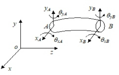
Rotor systems are generally composed of components such as wheel discs, shafts and supports. The wheel discs is generally modeled by a concentra- ted mass model, the support equivalent is orthogonal stiffness and damping, the rotating shaft is modeled by Timoshenko beam elements, considering the shear deformation of the rotating shaft, ignoring the axial deforma- tion of the rotor system, and the generalized coordinates of each unit are the displacement and rotation angle of the nodes at both ends, as shown in Figure 1.
Each Timoshenko cell has 8 degrees of freedom, respectively the displa- cement and angle of the two end nodes, then in the complex domain, the generalized coordinates of the two end nodes are expressed as: qA = [xA−jyA, θxA+θyA]T (1)
Equations and mathematical formulas are available in the original paper PDF.
Figure 1: Timoshenko beam element.
where xA, yA, θxA, θyA represent the displacement and angle of node A, respectively, and xB, yB, θxB, θyB represent the displacement and angle of node B, respectively.
The rotor system is discretized into a finite element dynamic model com- posed of N nodes and N-1 Timoshenko elements, when the rotor system has an imbalanced fault, let the imbalance fault occur at the node hi ( i=1, 2,..., n), then the equation of motion of the rotor system under the imbalance fault can be written as:
where qe is the generalized displacement vector of the rotor system under eccentric force only, M is the mass matrix, ω is the rotor speed, J is the pole moment of inertia matrix, C is the damping matrix, K is the stiffness matrix, Fei is the imbalanced force vector at node hi, H2hi−1 is the location vector of the fault, the line 2hi −1 is 1, and the rest is 0.
In equation (3), qe and Fei are expanded by harmonics to yield:
[k]ejkωt (4)
where qe
[k], Fei[k] denotes the harmonic component of the kth order. The power frequency components in equation (4) and equation (5) are separa- ted, that is, the first-order harmonic components, according to the harmonic balance principle:
n X
[−ω2M + jω(ωJ + C) + K]qe
A Model-Based Method for Imbalance Identification of Aero-Engine Rotor 35 Note E[k] = [−k2ω2M + jkω(ωJ + C) + K]−1 is the frequency response function matrix, Then the rotor imbalance fault for the first-order power frequency is:
[1] n X
qe
n X
q[1]
H2hi−1F[1]
ei (8)
where q[1]
e(2hv−1), E[1]
(2hv−1) is line 2hv −1 of qe
[1], E[1]. The knowable equation (8) can form an equation of n + 1.
Suppose that the rotor imbalance fault occurs at the node bhi ( i=1, 2,…, n), and then take the data substitution equation (8) at n measurement points to form an n-element primary equation system for bF
Pn
q[1]
(2h1−1)
[1] ei q[1]
Equations and mathematical formulas are available in the original paper PDF.
(2h2−1)
[1] ei . . .
Pn
q[1]
[1] ei
Equations and mathematical formulas are available in the original paper PDF.
(2hn−1)
After solving bF
[1] ei by equation (9), the deviation 1 is calculated using the data at the remaining measurement point (n + 1).
n X
[1] ei (10)
(2hn + 1−1)
H2bhi−1bF i = 1 When the 1 is the smallest, then bhi = hi(i = 1, 2, . . . , n),at this time node bhi ( i=1, 2,…, n) is where the imbalance fault occurs.
Rotor Imbalance Fault Parameter Identification Method Based on Sensitivity Method The equation of motion of the rotor system under known imbalance fault can be written as:
0ω2ejθiejk0ωt, where Ai is the amplitude of the imbalanced fault, θi is the phase of the imbalanced fault, and k0 is the characteristic fre- quency order of the imbalanced fault, that is, the first order. Note that the imbalance fault parameters that need to be identified are:
p = [A1 θ1 A2 θ2 . . . An θn] (12) Then the first-order harmonic component of the time domain response can be expressed as a function of the imbalanced fault parameter to be identified, i.e.:
p
where Q represents the first-order harmonic component of the time domain response, then rotor imbalance fault parameter identification can be transfor- med into an optimization problem:
Min
p
p
p
2 2, R
R
Equations and mathematical formulas are available in the original paper PDF.
represent the first-order harmonic components of the time- domain response of the rotor imbalance fault experiment and the first-order harmonic components of the time-domain response of the simulation analy- sis, respectively, and R
p
are called the residual terms. Initialize the rotor imbalance fault parameter to p0. Remember: (15)
Then the first-order Taylor expansion of the experimental value of the first-order harmonic component Qe at p0 is:
p0
+ S (pe −p0 ) (16) where S is called the sensitivity matrix, and pe is the experimental value of the rotor imbalance fault parameter, then the correction iteration of the imbalance fault parameter is:
pi
+ S (pi + 1 −pi ) (17) where pi is the parameter value after the ith iteration, and pi + 1 is the parameter value after the i + 1 iteration, Namely:
) (18)
pi
where S−1 is the inverse matrix of the sensitivity matrix, considering the problem of sensitivity matrix singularity, S takes the generalized inverse to obtain:
) (19)
−1sT (Qe −Qp
pi
When
2 < ε, it is considered that the convergence criterion has pi
1pi been reached and the iteration is completed. At this point, pi + 1 or pi
A Model-Based Method for Imbalance Identification of Aero-Engine Rotor 37
is approximately equal to the experimental value of rotor imbalance fault parameters pe.
Through the above method, the rotor imbalance fault position and ampli- tude and phase are obtained, and then the imbalance is increased at the imbalanced fault position, where the imbalance amplitude is the amplitude of the rotor imbalance fault, and the imbalance phase is the opposite direction of the rotor balance fault phase, which can basically eliminate the imbalance of the rotor system, thereby effectively suppressing the vibration of the rotor system.
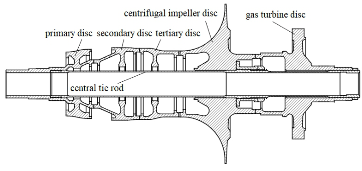
MODEL VALIDATION The structure of the simulation aero-engine gas generator rotor is shown in Figure 2. The rotor is designed with reference to the structure of the real aero-engine gas generator rotor, without the blade structure. The simulation rotor mainly consists of five wheel discs and a central tie rod. The exteriors, from left to right, are compressor primary disc, secondary disc, tertiary disc, centrifugal impeller disc and gas turbine disc, which are pressed and fixed internally by the central tie rod; The support positions are located at both ends of the rotor.
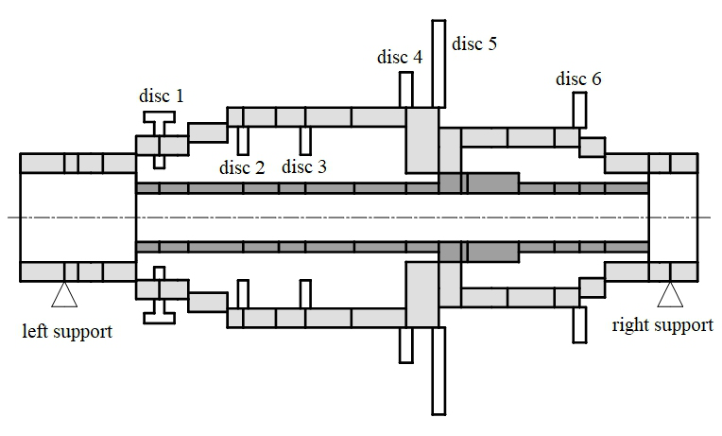
The finite element model node division of the simulation aero-engine gas generator rotor is shown in Figure 3 (schematic diagram, not drawn to scale for clarity). The five wheel discs (light-colored part) is divided into 21 shaft segments and 22 nodes, of which the frames of the compressor primary disc, secondary disc, tertiary disc are simplified to disc 1, disc 2 and disc 3 respe- ctively; The wheel disc of the gas turbine is simplified to disc 6; Considering the large size of the centrifugal impeller disc, the distribution distance along the axial direction is long and uneven, so it is simplified to two discs, namely disc 4 and disc 5. Considering the moment of inertia and gyroscopic effect of disc 1∼6, it is simplified to a concentrated mass point and applied to the position of node 6, node 9, node 11, node 13, node 14 and node 18 of the
Figure 2: The simulation aero-engine gas generator rotor.Figure 3: The finite element model.
beam element respectively. The central tie rod (dark part) is divided into 15 shaft segments and 16 nodes. According to the actual mating relationship of the gas generator rotor, nodes 5, 14, 15 and 20 of the five wheel discs are connected to nodes 1, 9, 10 and 16 of the central tie rod with an approxi- mate rigidity, respectively. The rotor is supported by 2 bearings, which are simplified to equal stiffness elastic supports, of which the stiffness of the left support is k1=1.46×10⁷N/m, located at node 2; The stiffness of the right support is k2=5.84×10⁶N/m, which is located at node 22. In summary, the finite element model of the established simulation gas generator rotor has a total of 36 shaft segments and 38 nodes.
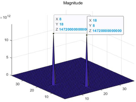
The simulation gas generator rotor model sets an imbalance fault at node 8 and node 18, and the imbalance fault parameters are shown in Table 1. Using the vibration displacement response at the measurement point, the above principle is used to identify the imbalanced fault position, and the change diagram of 1/1 with the node is obtained, as shown in Figure 4.
As can be seen from Figure 4, the abscissa and ordinate coordinates of the maximum value of 1/1 are 8 and 18, so the imbalanced fault occurs at nodes 8 and 18. The results of the calculations are consistent with the hypothesis. After identifying the rotor imbalance fault location, the amplitude of the initial imbalance fault is 100 g·mm, and the initial phase of imbalance is 45
.
Table 1. Imbalance fault parameters.
Table available in the original PDF paper.
Node location Amplitude(g·mm) Phase(
)
8 2 90 18 50 90
A Model-Based Method for Imbalance Identification of Aero-Engine Rotor 39
Figure 4: The change diagram of 1/1 with the node.
The rotor imbalance fault parameter identification method based on sensi- tivity method is used to identify the amplitude and phase of the imbalanced fault, and the imbalance fault parameter identification results are shown in Table 2.
It can be seen from Table 2 that in the absence of noise, based on the finite element model of the simulation gas generator rotor, the rotor imbalance fault location method based on the harmonic balance method can accurately identify the location of the imbalance fault by using the vibration displa- cement time domain response at the measurement point. On the basis of identifying the imbalanced fault location, the rotor imbalance fault parameter identification method based on sensitivity method can accurately identify the amplitude and phase of the imbalanced fault, and the recognition error can reach less than 1%. Based on the identified imbalance fault location, ampli- tude and phase, the imbalance is added at nodes 8 and 18 of the simulation gas generator rotor system, which can basically eliminate the imbalance of the rotor system, thereby effectively suppressing the vibration of the rotor system.
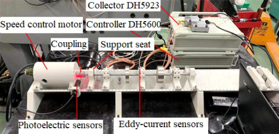
EXPERIMENTAL VERIFICATION In order to verify the effectiveness of the rotor imbalance identification method proposed in this paper, a rotor experimental system was built with
Figure 5: Rotor test bench.
the single-span and double-disc rotor system as the research object, as shown in Figure 5, the rotor system imbalance fault test is carried out.
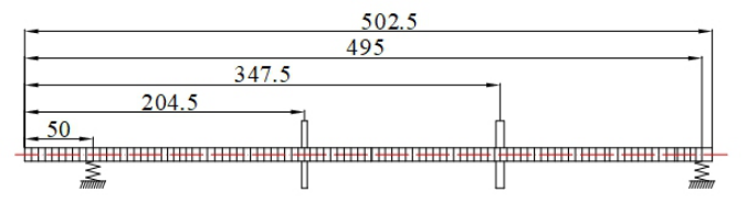
According to the above rotor experimental system, the finite element model of single-span and double-disc rotor system is established, as shown in Figure 6.
The specific parameters of the finite element model are as follows, the total length of the rotor system is 502.5mm, divided into 101 shaft segments, a total of 102 nodes. Among them, the shaft diameter is 10mm, the density is 8000kg/m3, and the elastic modulus is 210Gpa; The rotor disc 1 has a diameter of 78mm, a thickness of 19mm, a mass of 0.5kg, and the center of the disc is located at node 42; the rotor disc 2 has a diameter of 78mm, a thickness of 25mm, and a mass of 0.8kg, and the center of the disc is located at node 71; the rotating shaft is supported by two plain bearings, respectively located at nodes 11 and 101, simplifying the support equivalent to equal stiffness elastic support, the supporting stiffness at node 11 is 1.15×10⁵N/m, and the supporting stiffness at node 101 is 1×10⁵N/m.
Add an imbalanced screw on the rotor disc 1, where the imbalance screw mass is 2g, the radial distance of the imbalanced threaded hole is 30mm, and the imbalanced phase is 22.5
. The rotor stable speed is set to 2000rpm through the turntable controller, and when the rotor speed is sta- ble at 2000rpm, the horizontal vibration displacement signal of the shaft at the measurement point of the imbalance fault is collected, and the two
Figure 6: Finite element model of single-span and double-disc rotor.
A Model-Based Method for Imbalance Identification of Aero-Engine Rotor 41
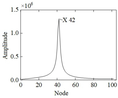
measurement points are located at node 26 and node 86. Using the vibra- tion displacement response at nodes 26 and 86, based on the finite element model of single-span double-disc rotor, the rotor imbalance fault identifica- tion method based on harmonic balance method was used to identify the imbalanced fault position, and the change diagram of 1/1 with the node was obtained, as shown in Figure 7.
As can be seen from Figure 7, the abscissa of the maximum value of 1/1 is 42, so the imbalance fault occurs at node 42, that is, at the rotor disc 1, which is the same as the imbalance fault location set in the experiment. After identifying the rotor imbalance fault location, the amplitude of the initialized imbalance fault is 3000g·mm, the initial phase of the imbalance is 90
, and the rotor imbalance fault parameter identification method based on sensitivity method is used to identify the amplitude and phase of the imbalanced fault, and the identification results of the imbalanced fault parameters are shown in Table 3.
It can be seen from Table 3 that the rotor imbalance fault location method based on harmonic balance method can accurately identify the location of the imbalanced fault by using the collected vibration displacement response. On the basis of identifying the imbalanced fault location, the rotor imbala- nce fault parameter identification method based on sensitivity method can accurately identify the amplitude and phase of the imbalanced fault, and the recognition error can reach less than 5%. Based on the identified imbalance fault location, amplitude and phase, add the imbalance amount on the rotor disc 1, where the imbalance amplitude is 59.267g·mm and the imbalance
Figure 7: The change diagram of 1/1 with the node.Table 3. Imbalance fault parameter identification results.
, which can basically eliminate the imbalance of the rotor system, thereby effectively suppressing the vibration of the rotor system.
CONCLUSION
In this paper, a finite element model of the simulation aero-engine gas generator rotor is established, and the time-domain response of vibration displacement collected at specific measurement points is used to successfully identify the rotor imbalance fault location, amplitude and phase based on the model-based identification method of aero-engine rotor, and the identifica- tion error can reach less than 1%, and the imbalance of the rotor system is successfully eliminated, thereby effectively suppressing the vibration of the rotor system. In this paper, the effectiveness of the above method is verified by the rotor experiment bench experiment. The experimental identification results show that the rotor imbalance fault identification method propo- sed in this paper can effectively identify the rotor imbalance fault position, amplitude and phase, and the recognition error is kept below 5%, and the imbalance of the rotor system can be basically eliminated, so as to effectively suppress the vibration of the rotor system.
ACKNOWLEDGMENT
The research work is supported by the National Science and Technology Major Project (2017-I-0006-0007), the National Natural Science Foundation of China (52005100), the National Science Fund for Distinguished Young Scholars (52125209), the Key R&D Plan of Jiangsu Province (BE2022158), the Jiangsu Association for Science and Technology Young Talents Lif- ting Project (TJ-2022-043), the Zhishan Youth Scholar Program of SEU (2242021R41169) and the Fundamental Research Funds for the Central Universities.
REFERENCES
Castro, H., Cavalca, K. L., Camargo, L., Bachschmid, N. (2010). Identification of unbalance forces by metaheuristic search algorithms. Mechanical Systems & Signal Processing, 24(6), 1785–1798. Deng Wangqun, Fan Panpan, Yuan Sheng, He Ping, Xia Kun. (2016). Analysis of
critical speed adjustment measures of high-speed rotor of turboprop engine. Gas Turbine Test and Research, 29(5), 5. Deng Wangqun, Gao Deping, Liu Jinnan, Lei Mozhi. (2005). The role of rotor highspeed dynamic balance technology in vibration damping of turboshaft engine. Journal of Aerospace Power, 20(1), 8. Deng Wangqun, Nie Weijian, Xu Youliang, Yuan Sheng, Liu Wenkui. (2018). Resea-
rch on vibration failure analysis and balancing technology of high-speed flexible rotor of turbofan engine. Gas Turbine Test and Research, 31(1), 8. Deng Wangqun. (2006). Experimental study on dynamic characteristics and highspeed dynamic balance of flexible rotor of aero-engine. (Doctoral dissertation, Nanjing University of Aeronautics and Astronautics). Feng Jianpeng, Zhao Xiaoyong. (2018). Research on phase detection method of
vibration imbalance of aero-engine. Gas Turbine Test and Research, 31(3), 5.
A Model-Based Method for Imbalance Identification of Aero-Engine Rotor 43
Hou, L., Chen, Y., Fu, Y., Chen, H., Lu, Z., Liu, Z. (2017). Application of the hb– aft method to the primary resonance analysis of a dual-rotor system. Nonlinear Dynamics, 88(4), 2531–2551. Li Luping, Lu Xuxiang. (2007). Vibration and treatment of turbine-generator sets.
China Electric Power Press. Liu Wenkui, Deng Wangqun, Lu Bo, Sun Yong, Tang Hubiao. (2019). Study on rotordynamics of cantilever power turbine with flexible transition section. Gas Turbine Test and Research, 32(2), 8. Sudhakar, G., Sekhar, A. S. (2011). Identification of unbalance in a rotor bearing
system. Journal of Sound & Vibration, 330(10), 2299–2313. Tang Hubiao, Deng Wangqun, Liu Wenkui, Song Mingbo, Feng Yi. (2021). Rotor unbalance response analysis and experimental study of aero-engine gas generator. Journal of Changsha Aviation Vocational and Technical College, 21(2), 5. Wei Yuan, Xu Wubin, Zhang Hongxian. (2011). Rotor balancing phase measure-
ment based on LabVIEW. Mechanical Design and Manufacturing (12), 3. Wu Liangsheng, Chao Huiquan, Zhang Shihai. (2012). Extraction of rotor unbalanced vibration signals based on least squares method. Machinery Design and Manufacturing, 000(002), 194–196. Zhang Ruxin, Wen Guangrui, Zhang Zhifen, Xu Bin. (2019). Multi-point unbala-
nce identification of rotor system with GA-PSO method. Vibration. Testing and Diagnostics, 39(4), 11. Zhao, S., Ren, X., Deng, W., Lu, K., Fu, C. (2021). A transient characteristic-based balancing method of rotor system without trail weights. Mechanical Systems and Signal Processing, 148, 107117.
LISTED IN THE AHFE DIGITAL BOOKSTORE CATALOGUE
Explore the complete digital volume
Human-Centered Aerospace Systems and Sustainability Applications
Read this individual research paper free through the original publisher, or explore the full digital proceedings book.
ISBN 978-1-958651-74-2
Explore this ISBN in the AHFE Bookstore ↗Listed in the July 2026 bookstore catalogue; search by ISBN to confirm current availability · Digital book purchase optional