Mayank Badola, Dibakar Sen (2026). Simulating Force-Posture Co-Evolution in Horizontal Pushing Task Using DHM. In: Human Factors in Simulation, Software and Systems Engineering. AHFE Open Access, vol. 220, pp. 123–134. https://doi.org/10.54941/ahfe1007700
Ergonomic analysis of a manual material handling task is essential to evaluate the musculoskeletal disorder risk involved. Digital Human Model (DHM) simulation is one of the techniques used to identify potential hazards. In the current method, the user provides force and posture, and subsequently, the simulation computes the joint stresses. In most simulations, the force and the posture are independent; therefore, they are mutually irresponsive. The work presented here argues that the responsive co-evolution of force and posture is essential for realistic performance assessment. It is known that musculoskeletal loading is affected by the force direction. Therefore, a wrong estimation of applied force direction could lead to an inaccurate assessment of joint stresses. In this work, first, we performed experiments to identify the unknown variables influencing the applied direction of force. Subsequently, based on the obtained data, a mathematical force model is developed that correlates the applied direction of the force with the position of the point of application of force and magnitude. The force model is then integrated into an existing DHM; this removes the need to provide the force direction manually. Using a physics-based object response model for a linear spring and box on a table experiencing static and dynamic friction, two illustrative task simulations that do not require any force specification are presented. The necessary exertions and associated biomechanical efforts can be derived from the result.
The DHMs in the literature mainly concern kinematics-based posture predictions, which can be superimposed with external force for safety assessment. In natural hu-man performance, posture emerges with the force while interacting with the environment (Simpson et al., 2011). Therefore, inclusion of the realistic interaction and posture-force relationship is necessary for meaningful simulation.
In many advanced DHMs like Jack (Badler et al., 1993), the posture for a task is obtained using inverse kinematics; then a known load is applied to evaluate its biomechanical consequence. However, the posture itself is insensitive to the applied force. Human body has redundant kinematic DOF; this enables inter and intra-individual performance variation in terms of posture and applied force (Park et al., 2005). It is suggested in Robert and John (2003) that the variation should be introduced through rich environmental interactions. SANTOS (Abdel-Malek et al., 2008) predicts the Received February 20, 2026; Revised April 9, 2026; Accepted April 27, 2026; Available online July 20, 2026
124 Badola and Sen posture using multi objective optimisation for maintaining the joint torques under acceptable limits to obtain task sensitive and realistic postures.
In this paper, we argue that the practice of specifying an external force vector for a posture by the user in a simulation does not capture real situation. During human performance, the force of interaction manifests on the objects it operates on as per the laws of physics. The reaction from the object/environment affects the human as per the principles of biomechanics. Here we argue that human performance is outcome driven, since the force vector of exertion is not directly observable; using force sensors on skin, joints and muscles, human estimates a qualitative attribute of the exerted force and activates muscles accordingly to manipulate objects. Thus an exertion in a perceived direction with gradual increment of perceived magnitude is believed to be the strategy of human performance.
We first identify the redundancy of human’s action and interaction during task execution. Then an empirical expression relating the direction, magnitude and location of an applied push force by a person is derived. This force model, together with a physics-based object-response model, is then employed to simulate the co-evolution of force, posture and object-response during quasi-static push-pull tasks.
FUNDAMENTALS OF INTERACTION Humans derive their ability to exert/resist force at the hand from the activation of the muscles which manifest as joint torques. Redundancy in the kinematic structure and the variability of the joint torques make relation among posture, force and joint-torque an ill-posed situation; we refer to this as redundancy of action. Although response of the physical world is governed by laws of physics, actual response of an object for any action by human is uncertain because exact exertion and parameters governing an objects behaviour are both unknown. This we refer to as unpredictability of response.
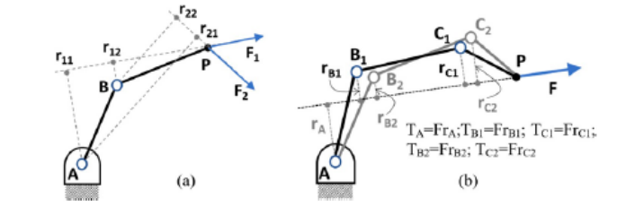
Redundancy in Human Action Let us consider a dyad ABP shown in Figure 1(a), which can represent a human arm with A as the shoulder, B as the elbow and P as the hand where force F1 and F2 are being applied. It is easy to observe that for a given work- location P, a posture of the ABP-dyad is fixed as the inverse kinematics has a closed-form solution. However, for applying each of F1 and F2, the torques necessary at joints A and B are distinct; for F1, TA = F1 ∗ r11, TB = F1 ∗ r12; and for F2, TA = F2 ∗ r21, TB = F2 ∗ r22. Conversely, with a different sets of joint torque, one can exert different force vectors at a given location. Due to this redundancy, it is impossible to assess stress at joints with incomplete knowledge about the force, even if the posture is accurately known.
In the presence of postural redundancy, when the kinematic degrees of freedom is higher than the minimum necessary for the reaching task, a given force F at the end-effector induces different joint torques, albeit different force will induce different joint torques as well as shown in Figure 1(b).
Figure 1: Applied torque and resultant force at the end effsector.Figure 2: Schematic of the arm pushing a box.
Unpredictability of the Object Response For a task involving exertion on a static object, the reach posture before exertion (F = 0) is likely to change with exertion to minimise the cumulative effort over all the joints. This, in principle, is computable, provided the magnitude and direction of the external force is known. This is available for lifting tasks (objects weight), but not for push/pull tasks (Ayoub and McDaniel, 1974) because, the interaction between the object and support surface determines the force required, which is practically unknown due to the multiplicity of factors that affect it; this makes the response unpredictable.
Let the A-B-C-P chain (Figure 2) represents the arm pushing a box kept on a table; µ is the coefficient of friction between the box and the table. F is the push force applied with a deviation of α from the horizontal direction. Consequently, the box would either tilt about point O when
Equations and mathematical formulas are available in the original paper PDF.
126 Badola and Sen Thus, condition of tilting due to a push is rW /rF ≤ µ/(cos α + µ sin α). Here, rW depends upon the geometry of the box. The center of gravity is non-observable to the user; so, rW is unknown. The α and rF depend upon the selected line of action of the effort in which the user is visually aware of only the point of application; µ is an empirical parameter. The α that would produce minimum joint stresses, may not produce the desired outcome; for certain α, P might starts moving with a lower F, but it might tilt rather than slide; thus, neither the force, nor the response of the object can be prescribed in a simulation with a given posture (observable). We believe that the force experienced by the subject emerges from the iterative interaction manoeuvres.
Statics of Interactions The problem of pushing and pulling in manual material handling has been studied since long (Daams, 1993). Empirical characterisation of the standard help in defining safe situations in design. Although it is known that actual push for a horizontal push task has nontrivial vertical components, a mechanistic insight is necessary for simulating similar situations in a DHM. Since slippage of the foot or hand leads to accidents, a better understanding of the coupling among the posture, action and environment is important. In the following, we consider canonical interaction scenarios to derive the conditions of static equilibrium and slippage.
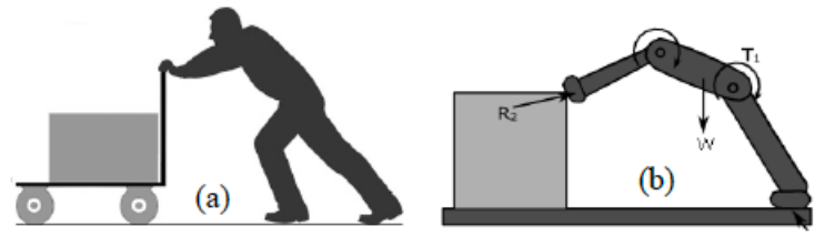
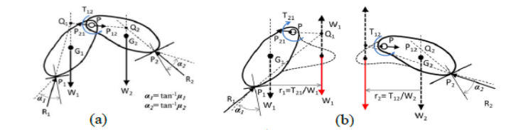
Figure 3: Cart pushing scenario (a) human posture (b) kinematic representation of posture.Figure 4: Force components and free body diagrams.
The scenario of pushing a cart using the standardised posture of an extended arm and un-flexed supporting leg is shown in Figure 3(a), along with the associated articulated rigid body system under the influence of forces and torques, which should be in equilibrium as shown in Figure 3(b). For the sake
Simulating Force-Posture Co-Evolution in Horizontal 127 of the present analysis, we simplify the model further using only two segments and one hinge, as shown in Figure 4 and derive the equilibrium conditions.
The Figure 4 shows a mechanical arrangement where two rigid bodies, hinged at P, are supported on the environment at the points P1 and P2 with coefficients of friction µ1 and µ2 with the corresponding angles of friction being α1 and α2. The body-2 is acted upon by a torque T12 from body-1; W1 and W2 are the weights, and R1 and R2 are the reaction forces at P1 and P2 to keep the body under equilibrium. P12 and P21 are reaction forces at P as experienced by the two bodies. The reactions from the contact interfaces and joint reactions at P are determined using force and moment balance conditions as follows.
21 1 12 2 21 12
P R P R P P W P R W P R P P
0; 0; ; 0; 0; ;
1 21 1 2 12 2 21 12
21 1 1 1 21 1 21 1
x x y x x x y y
12 2 2 2 12 2 12 2
x x y x x x y y
( ) ( ) ( ) 1 12 2 2 2 2 2 3 2 ; ; x x x x y y D T W G p D p p D p p = − + − = − = − And 3 2 2 3 C D C D ∆= ∗ − ∗ Then, we get
P C D C D P R R
21 1 2 2 1 12 1 2
P C D C D P
21 1 3 3 1 12
y y
R P W R P W
and .
1 21 1 2 12 2
y y y y
If either the resulting R1 or R2 fall outside the friction angle at their respective points of contact, it would experience slip. For understanding of the effect of T12 on R1 and R2, we consider the free-body diagrams as shown in Figure 5. The lines of W1, R1 and P21 must be coincident on some point Q1 for the equilibrium of body-1; similarly, Q2 for body-2. P12 and P21 being equal and opposite, Q1, P, and Q2 are collinear. When T12≠0, then we consider T12 on body-2 and T21 on body-1 for their respective free bodies. The effect of T21 and W1 on body-1 parallel-shifts line of W1 by r1 = T12/W1; similarly, the line of W2 on body-2 is shifted by r2 = T21/W2. When T21 tends to open out the angle P1PP2, it also tends to R1 and R2 away from the normal at P1 and P2. Thus, when some extra torque is exerted at the joint, it increases the chance of slippage; the applied force at hand and the resistance at the foot would increase, but their directions are not controllable when there is only one articulated joint. This would explain why we need to consider at least two articulated joints, as shown in Figure 3(b).
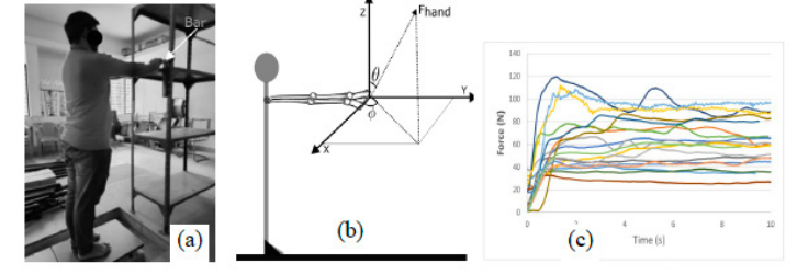
Figure 5: Push-pull with fixed and erect posture (a) setup (b) convention for directions (c) variation of force.
This section established that the applied force for given configuration during static interaction is unknown because of unobservable joint torques. This indeterminacy of force makes response of the object and operator unpredictable.
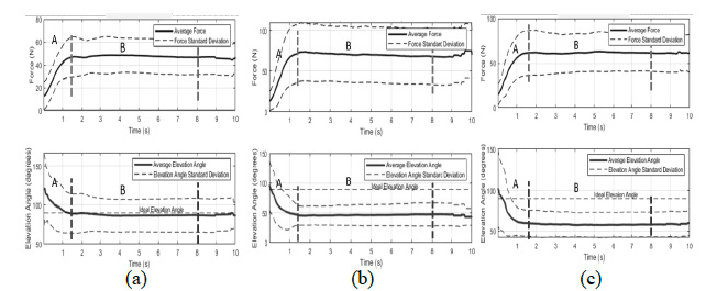
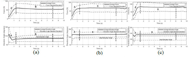
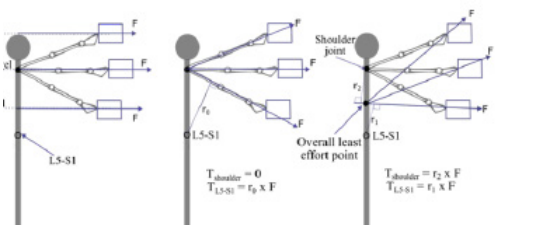
Figure 6: Mean and standard deviation of magnitude and elevation of push force at (a) elbow (b) shoulder (c) head.Figure 7: Mean and standard deviation of magnitude and elevation of pull force at (a) elbow (b) shoulder (c) head.Figure 8: Possible exertion patterns (a) all horizontal puts both shoulder and waist under stress (b) along arm good for shoulder not for waist (c) natural preference optimizes stresses on multiple joints.
EXPERIMENTAL DETERMINATION OF DIRECTION OF EXERTION The subject stood at a position to be able to reach the horizontal bar on a shelf without bending the elbow, as shown in Figure 5(a), on a force plate, AMT (BP400600-OP-1K-STT), which provided ground reaction force in the x, y, and z directions at a rate of 50 Hz. The force vector exerted at the hand was indirectly measured using a force plate as given in Dutta et al. (2012) and Faber et al. (2013). The experimental setup and convention for measuring elevation (θ) and azimuth (ϕ) are shown in Figure 5. Eight subjects, seven male and one female volunteer participated in the experiment. Subjects were asked to apply a high horizontal push and pull force on a bar fixed on a frame as per their own judgement. They were instructed to relax after for 10 seconds. A rest for 5 minutes between the trials was provided to minimise the effect of fatigue.
The subjects performed the task at their respective elbow, shoulder and head levels. Representative data is presented in Figure 6 and Figure 7. It can be observed that, as mentioned in Hoffman et al. (2007), subjects did not apply a horizontal force but at a positive elevation. Although the trends of the plots are similar, there are significant difference in the associated values for the three heights considered. There is significant subjective variation, indicated by standard deviation plots. Similar trends are reported in De Looze et al. (2000) and Granata and Bennett (2005).
If the subjects applied force actually as per the instruction, we get the situation as in Figure 8(a) (Ji et al., 2022). Kerk et al. (1994) mentioned that this is not true. Abel and Frank (1991) opined that the reactive force was directed towards the shoulder to minimise effort as shown in Figure 8(b). But this would put the waist at severe disadvantage! We did not observe a horizontal force at the shoulder level; it is more so for the elbow level! Probably subjects’ intent was modulated towards balancing the efforts at multiple joints (Figure 8(c)). Thus, we need model for estimating the direction of applied force when the intent is horizontal!
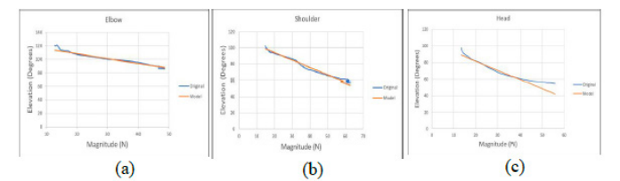
EMPERICAL MODEL OF DIRECTION OF EXERTION BY DHM The general pattern of exertion, as can be observed from Figures 6 and 7, is that both the magnitude and the elevation angles vary monotonically up to a point, then it saturates to a stable value. Although the saturation value varied among subjects, all of them saturated within first fifty readings or 0.5 sec. A bilinear interpolation model was developed for the transient portion of the curves. The force versus elevation linearized relations are illustrated in Figure 9.
Figure 9: Linear fit of variation of applied direction with magnitude of exertion.
The general form of the model is ( ) ( ) 1 2 i i i f H M f H θ = × + , where M is the magnitude of applied force, θi is the elevation angle for height Hi of the intended horizontal push. Since the actual numerical value of force is not perceived, the subject exerts gradually increasing force to achieve the desired outcome. Since the response of the object depends upon the actual force vector, varying direction with exertion with magnitude and location affects the outcome. The above model of exertion is thus a simplistic representation of the interaction. From the data of the experiments conducted, the following results are obtained for the push endeavour.
θ
M
M
M
elbow
We observed a decrease in coeffcient values with increase in level. Assuming a linear relationship between coefficients corresponding to f1(Hi) and f2(Hi), for simplicity, we get f1(H)i = (−0.08 − 1.02H) and f2(H)i = (156.20 52.51H). The final relationship among elevation, height and magnitude used in our DHM is as follows 0.08 1.02 156.20 ( ) ( ) 52.51 H M H θ = − − × + −
SIMULATION OF PULL AND PUSH TASKS USING DHM DHM simulations often use the joint effort as a measure of quality of a posture. The joint effort is the ratio of torque acting at the joint and torque
Simulating Force-Posture Co-Evolution in Horizontal 131 bearing capacity of the joint; joint torques in turn depend upon the posture and forces acting on the DHM, viz. external load, segmental body weights and inertia (Chaffin et al., 2006). In kinematic-based posture prediction systems, the causal connection between posture and force is not modelled. For an new scenario when posture and force is unknown, it takes multiple iterations to develop the posture and force combination for realistic joint efforts (Wolf et al., 2019). Optimization based schemes (Maurice et al., 2022, Marler et al., 2012, Eazhil and Sen, 2020) mitigates this problem by computationally derived optimal posture that minimized joint efforts a given force.
Our simulation task involved exertion with iterative increment of the force. For each level of force its direction is computed as per the above model; response of this force on the posture is determined by the effort optimization with balance maintenance scheme given in Eazhil and Sen (2020); the response of the object due to the force is computed using the underlying physics.
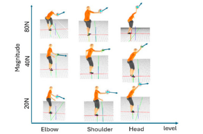
Figure 10: Posture prediction using the force model.
Figure 10 depicts the postures obtained using the above force model when the applied force (magnitude) is increased gradually for three different heights. The posture prediction algorithm minimizes the cumulative joint efforts (torque exerted/capacity of the joint), while maintaining balance, for a given force vector acting on the hand.
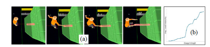
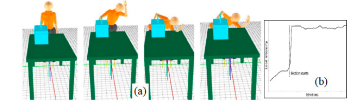
The example shown in Figure 11 illustrates a linear force displacement behaviour of a spring under a pull force. It can be noticed that the posture continuously changes with increasing exertion. Also, the overall joint effort (indicated as load intensity in the graph) continues to increase in a non-linear fashion. In the second example (Figure 12), the task of pushing a box of 16 kg
132 Badola and Sen on a table with coefficient of friction 0.3 was simulated. Here in the first phase force builds up until the motion starts. At that instant, a lower coefficient of (dynamic) friction gets activated resulting in lesser force requirement. But as the object recedes fast, posture for pushing gets awkward resulting in higher stress in the lower back which however maintains a steady value.
Figure 11: Pulling a linear spring (a) force-posture co-evolution (b) overall joint effort for force-posture combination.Figure 12: Pushing a 16 kg box (a) force-posture co-evolution (b) low-back effort for force-posture combination.
CONCLUSION
Even though the influence of the direction of the force on the musculoskeletal load is significant, the literature survey shows a lack of rigour in considering the force direction in simulations. In this study, we established the mechanics which allows the applied force direction to be a variable for a posture. The difference between applied and intended exertions are reported in literature; but we could not find a model for DHM application. Therefore, we conducted experiments to identify the pattern in the actual force direction for a given intended exertion task. The results showed a striking similarity in the exertion tasks for different levels of magnitude and location; directions and magnitudes of forces monotonically changed consistently across subjects for first 0.5 sec then stabilized to a value which varied across subjects. The mean of the values was used to develop a bilinear exertion model which was then used for posture prediction for horizontal push tasks in the sagittal plane using a in-house DHM which ensures optimal joint stress while maintaining balance for any applied force. Although the prescribed task was horizontal
Simulating Force-Posture Co-Evolution in Horizontal 133 push, the DHM evolved the posture through gradually increasing the force as per the exertion model. Thus, the simulation demonstrated capability co-evolution of exertion and posture for the push and pull tasks. This approach, we believe will provide a more realistic estimate of joint stresses than a deterministic strategy which does not distinguish between actual and intended exertions.
ACKNOWLEDGMENT
The authors would like to thank the volunteers who participated in the experiment.
REFERENCES
Abdel-Malek, K., et al. (2008). Santos: a digital human in the making. Technical Report. https://dtic.minsky.ai/?query=ADA542025 Abel, EW, Frank, T.G., (1991). The design of attendant propelled wheelchairs.
Prosthetics and orthotics international 15(1): 38–45. Ayoub, M.M., McDaniel J.W., (1974). Effects of operator stance on pushing and pulling tasks. AIIE Transactions 6(3): 185–195. Badler, N., Phillips C. B., Webber B. Webber L., (1993). Simulating humans: computer
graphics animation and control. Oxford University Press. Chaffin, D. B., Andersson G., Martin B.J. (2006). Occupational Biomechanics. John Wiley & Sons. Daams, B. J. (1993). Static force exertion in postures with different degrees of
freedom. Ergonomics 36 (4): 397–406. De Looze, MP, et al. (2000). Force direction and physical load in dynamic pushing and pulling. Ergonomics 43 (3): 377–390. Dutta, T., et al., (2012). A biomechanical assessment of floor and overhead lifts using
one or two caregivers for patient transfers. Applied Ergonomics 43(3): 521–531. Eazhil, S.K., Sen, D., (2020). Estimating functional reach envelopes for standing postures using digital human model. Theoretical Issues in Ergonomics Science 21 (2): 153–182. Faber, G. S., et al. (2013). Estimating dynamic external hand forces during
manual materials handling based on ground reaction forces and body segment accelerations.” Jl Biomechanics 46(15): 2736–2740. Granata, K. P., Bradford C. B., (2005). Low-back biomechanics and static stability during isometric pushing. Human Factors 47(3): 536–549. Hoffman, S. G., Matthew P. R., Chaffin, D. B., (2007). “The relationship between
hand force direction and posture during two-handed pushing tasks.” in: Proc. Human Factors and Ergonomics Society Annual Meeting, Vol. 51, 928–932. Sage Publications Los Angeles, CA. Ji, X., et al., (2022). Analysis of Healthcare Push and Pull Task via JACK: Predicted Joint Accuracy during Full-Body Simulation. Applied Sciences 12(13): 6450. Kerk, C. J., et al. (1994). A comprehensive biomechanical model using strength,
stability, and COF constraints to predict hand force exertion capability under sagittally symmetric static conditions. IIE Transactions 26(3): 57–67. Maurice. L., et al., (2022). “Forward and Backward Reaching Inverse Kinematics (FABRIK) solver for DHM: A pilot study.” in: Proc 7th Intl Digital Human Modeling Symposium and Iowa Virtual Human Summit, Vol. 7. Univ of Iowa.
134 Badola and Sen Marler, T., et al. (2012). “Integration of strength models with optimization-based
posture prediction.” Advances in Applied Human Modeling and Simulation, CRC Press, 327–336. Park, W., et.al., (2005). Representing and identifying alternative movement techniques for goal-directed manual tasks. J Biomechanics 38(3): 519–527. Robert, W., John, L., (2003). “Variability in human behavior modeling for military
simulations.” in: Proc. of 12th Conf on Behavior Representation in Modeling and Simulation (BRIMS) Scottsdale, Arizona, USA. ISBN: 978-1-61567-168-7. Simpson, K. M., Munro, B. J., Steele, J. R., (2011). Effect of load mass on posture, heart rate and subjective responses of recreational female hikers to prolonged load carriage. Applied Ergonomics 42(3): 403–410. Wolf, A. W. et al., (2019). “Towards virtual assessment of human factors: A concept
for data driven prediction and analysis of physical user-product interactions.” in: Proc of the Design Society: International Conference on Engineering Design, Vol. 1, 4029–4038. Cambridge University Press.
LISTED IN THE AHFE DIGITAL BOOKSTORE CATALOGUE
Explore the complete digital volume
Human Factors in Simulation, Software and Systems Engineering
Read this individual research paper free through the original publisher, or explore the full digital proceedings book.
ISBN 978-1-964867-96-0
Explore this ISBN in the AHFE Bookstore ↗Listed in the July 2026 bookstore catalogue; search by ISBN to confirm current availability · Digital book purchase optional