Kim-Phuong L. Vu, Thomas Strybel, Vernol Battiste, Quang Dao (2025). Urban Air Mobility (UAM): Preliminary Task Analysis for a Terminal Corridor Vertiport Concept of Operation. In: Human Factors in Design, Engineering, and Computing. AHFE Open Access, vol. 199, pp. 1852–1862. https://doi.org/10.54941/ahfe1006996
Urban Air Mobility (UAM) refers to a transportation system of cargo and passenger in urban areas. UAM concepts include a mix of onboard, remotely operated, and increasingly autonomous operations (NASA, 2017). Although mature concepts will likely employ remotely piloted vehicle operations or increasing autonomous systems to operate a fleet or network of UAM vehicles, early UAM concepts will likely employ onboard human pilots operating the vehicles (Holbrook et al., 2020). In this paper, a task analysis is presented for a potential near-term UAM concept of operation. The use case is that of terminal UAM operations in a designated corridor with the following operators: UAM fleet manager, onboard UAM pilots, Tower Controller, Vertiport Manager and Automation. The results of the task analysis highlight the roles, responsibilities, and tasks performed by different operators that can inform future design of UAM terminal operations.
Urban Air Mobility (UAM) refers to a system of passenger and cargo transportation within an urban area that will be supported by a mix of onboard, remotely piloted, and increasingly autonomous operations (NASA, 2017). Early UAM operations will likely employ human pilots operating under conditions similar to those used for current visual flight rule (VFR) operations. Mature UAM operations will likely employ autonomous systems to allow for a network of aircraft using simplified vehicle operations and remote supervisory vehicle management (Holbrook et al., 2020). One concept important to the development of UAM is human autonomy teaming (HAT; Shively et al., 2017). HAT represents a deviation from the view where automation is used to perform routine human tasks. Instead, HAT takes a perspective in which the automation works together with the human operator to achieve system goals. One research challenge for HAT is to determine
Urban Air Mobility (UAM): Preliminary Task Analysis 1853
the roles and responsibilities for human and automation across the UAM maturity levels (Holbrook et al., 2020).
Task analysis is a method for breaking down a task into a hierarchy of goals, sub-goals and operations (Shepard, 2001). Similar analyses have been reported for midterm and mature UAM operations (e.g., Lee et al., 2025; Verma et al., 2022). In this paper, we performed a hierarchical task analysis for a potential near-term UAM concept of operation to examine potential coordinated interactions between different UAM operators and automation [i.e., Provider of Services for UAM (PSU)]. Specifically, the use case that we analysed was that of terminal area UAM operations in a designated corridor with the following human operators: fleet manager (FM), onboard UAM pilot-in-command (PIC), Tower Controller, and Vertiport Manager (VPM). All operators were assisted by automation in the form of a PSU (e.g., Rios, 2021). Specific goals, sub-goals, and operational plans were derived. The goal of this preliminary task analysis was to produce recommendations for improving operator interactions with the system, identify roles and responsibilities between the relevant UAM human operators and automation, and identify human factors issues and challenges for UAM operations.
CONCEPT: TERMINAL AREA COORIDOR OPERATIONS The concept of operation examined in this paper was that of terminal area corridor arrival operations at an existing airport. The following assumptions were made:
UAM vehicles are operating in a single corridor, with their approach path located near a major airport. The vertiport is located between parallel runways of that airport (e.g. Dallas Love Field; DAL).
All operator roles are fulfilled by human operators with the assistance of automation (i.e., the PSU). All communications are via voice.
The PSU has access to inter-arrival intervals to the active runway and the vertiport. The PSU provides information to all operators (FM, PIC, VPM and Tower Controller) regarding separation, conflicts and spacing. The PSU also assigns scheduled time of arrivals (STA) to all arrivals at the corridor entry point.
Immediately prior to corridor entry, speed, altitude, and required time of arrival (RTA) at the corridor exit point are provided to the PIC by the FM.
UAM traffic is assumed to be low in volume and operating entirely within class E/G airspace. There is no convective weather and visibility is clear. All UAMs are flying IFR routes.
The separation minimums between UAM vehicles and conventional aircraft are similar to that employed for fixed wing aircraft and helicopters in the terminal area: 1.5nm lateral and 500ft vertical. The separation minimums between UAM vehicles are 500ft within the corridor while managing to the RTA. At the exit point, PICs within the corridor are maintaining approximately 3nm in trail of arrival aircraft.
The corridor exit RTA provides a minimum of 1.5nm separation between the UAM vehicle and arrival aircraft to the active runway.
A letter of agreement (LOA) between the VPM and Tower Controller is in effect, in which the Tower Controller delegates authority to the VPM to clear UAM vehicles exiting the corridor at their assigned RTAs to cross the airport runway and land at a vertiport slot. The Tower Controller has authority, however, to suspend any or all UAM activity for safety reasons.
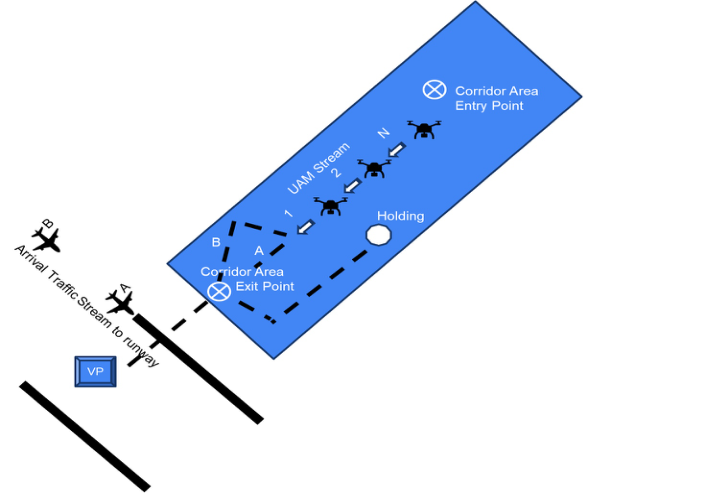
SCENARIO As illustrated in Figure 1, UAM vehicles will enter the corridor area from the northeast. The FM coordinates with the PSU regarding the management of multiple UAM vehicles within the corridor. The FM will have full control and responsibility for UAM operations, including but not limited to the UAM vehicle route separation and its position and spacing within the fleet.
Figure 1: Illustration of corridor operations near an airport. The corridor entry point is to the northeast and exit point in the south. There are two routes that the UAM vehicles could take to arrive at the exit point. Route A is a shorter path than route B. The closest runway is located south of the corridor exit point for arrival commercial aircraft (label traffic stream A, B). The vertiport for the UAM landing is on the other side of the closest runway, requiring the UAM pilots to receive a clearance from the vertiport manager to cross the runway for landing.
Onboard UAM PICs will manage the UAM vehicle within the corridor. They will adhere to route, speed and other spacing requirements set by the FM to meet their scheduled time of arrival (STA) entering the corridor and required time of arrival (RTA) exiting the corridor. The FM, with the aid of
Urban Air Mobility (UAM): Preliminary Task Analysis 1855
the PSU, will coordinate with air traffic control and the VPM to land the UAM vehicles at the designated vertiport while remaining separated from other air traffic in the vicinity.
Based on the LOA, the Tower Controller delegates to the VPM the responsibility to provide visual separation of the UAM vehicles between arrival aircraft landing at the airport runway. For example, in Figure 1 the VPM will clear UAM1 to land at a vertiport (VP) slot, after aircraft “A”. If UAM1 is achieving its RTA, the PIC will be cleared to the UAM arrival exit corridor point via route A. If UAM1 is early, it will be instructed to fly route B to the exit corridor point; if UAM1 is late, the vehicle may be sent to hold and handed back to the FM. Upon achieving the RTA at the corridor exit point UAM1 will be cleared cross the runway following aircraft A, and land at a specified VP slot. All following UAM traffic (e.g., UAM 2 and 3) are to maintain visual separation from the lead (i.e., UAM1) and to hover/hold when necessary. The PICs exiting the corridor will coordinate with the VPM to execute their landing at the vertiport.
OPERATORS: ROLES AND RESPONSIBILITIES The roles and responsibilities of each operator and that of automation (i.e., the PSU) are described in this section. A detailed task analysis for each operator is provided in the Appendix for the scenario described above.
Fleet Manager (FM) The FM works with the PSU to plan or replan arrival routes and schedules, as needed, to achieve company goals and objectives while meeting airspace constraints. The FM will also work with the PICs to manage to the STAs as provided by the PSU prior to corridor entry point and to the RTAs within the corridor until handoff to VPM.
FM Responsibilities:
Prior to Departure: Obtain approval from PSU for flight plan
Enroute: Ensure that PICs meet their STAs at the corridor entry point
Corridor entry point: Assign RTAs issued by PSU
Within Corridor: Ensure that all PICs comply with RTAs prior to handoff at coordination point and handoff arriving vehicles to VPM prior to the corridor exit point.
Pilot-in-Command (PIC) The PIC will work with the FM to develop and submit a flight plan to the PSU. In addition, the PIC will work with the FM to manage the STA to the corridor entry point and manage separation and spacing to achieve the RTA within corridor prior to handoff to the VPM. Any route modification must remain within the corridor.
PIC responsibilities:
Arrive at Corridor entry point at the STA assigned by the FM
Maintain visual separation from lead UAM vehicles (at least 500 ft) and separation from other UAM vehicles
Maintain arrival position and hold as needed
Arrive at corridor exit point, at RTA after cleared by VPM to cross runway.
Vertiport Manager (VPM) The VPM will ensure that all incoming UAM vehicles and commercial arrival aircraft are spaced at the airport runway based on the specified RTA. Given the LOA specified for this scenario with the Tower Controller, the VPM will also be responsible for clearing UAM arrivals to the corridor exit point (via route A or B), and to clear them to cross the runway and to land at a VP slot.
VPM responsibilities:
Ensure UAMs achieve their RTAs
Assign the UAM exit route (i.e., A or B in Figure 1) or hold
Clear the UAM to cross the airport runway and land at a VP slot.
Tower Controller The Tower Controller ensures separation of UAM and other air traffic by visual means, although UAM management is by exception due to the aforementioned LOA. The Tower Controller can, however, suspend any or all UAM activities for safety.
Tower control responsibilities:
Ensure standard arrival separation between UAM and other air traffic
Suspend UAM operation as needed.
Provider of Services for UAM (PSU) Our concept of the PSU is similar to previous NASA concepts of a PSU that will be utilized by UAM operators for exchanging information (e.g., Rios, 2021; Lee et al., 2025). Generally, the PSU is conceived as an automated service provider that supports flight planning, coordination, deconfliction, and spacing between all operators including air traffic control, thus allowing these operators to share flight information and maintain shared intent. In effect, the PSU allows all operators to be aware of other operations in the immediate airspace. In our simple scenario, the PSU responsibilities are limited to flight plan approvals submitted by the FM and determining spacing targets (e.g., STAs and RTAs).
PSU’s responsibilities:
Approves deconflicted flight requests from FM
Issue STAs: 3 miles separation at a corridor entry point
Issue RTAs: 1.5 miles separation from commercial arrival aircraft and UAM vehicle stream at exit point.
RESULTS & DISCUSSION In the near term, safe and efficient UAM operations can be achieved in light traffic and nominal weather conditions because the procedures are quite similar to current day, visual flight rule operations with small aircraft and
Urban Air Mobility (UAM): Preliminary Task Analysis 1857
rotorcraft. This conclusion is consistent with that of Verma et al. (2022) for their Use Case 0. Specifically, Verma et al. (2022) concluded that UAM arrivals could be accommodated with existing airspace procedures such as those for rotorcraft arrivals. However, as the density of either UAM vehicles or fixed wing traffic increases, the dependence on automated tools such as the PSU will increase and the reliability and trust of these tools will become a major factor in the success of the UAM program.
The reliance on automation for successful operations in higher density traffic is born out in the results of the task analysis. As shown in the Appendix, the most common task for all operators in the near term is monitoring. That is, the FM monitors all traffic in their fleet for compliance with the PSU instructions and air traffic control, and responds to information provided from both the PICs, and VPM. UAM PICs monitor traffic in their vicinity, FM communications, and instructions from the VPM and air traffic control. The tower controller while monitoring both streams of arrival traffic, because of the LOA, would only intervene as needed to maintain safe visual separation between the air traffic. If intervention is a rare event, then monitoring task would be in essence a vigilance task, which are known to have an impact on operator performance (Stearman & Durso, 2016).
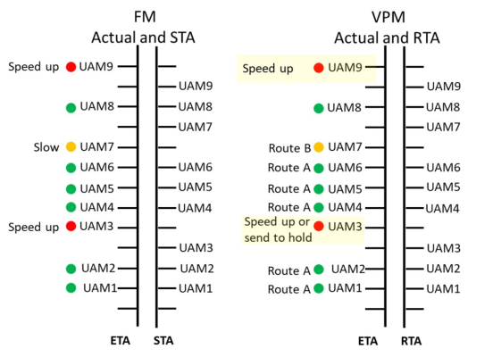
Figure 2: Illustration of a timeline display incorporating flight plan information coordinated by the PSU and ATM system. The left panel is for the fleet manager (FM) who will need to manage the UAM pilots to their scheduled time of arrival (STA) based on their estimated time of arrival (ETA). The FM will need to speed up or slow nonconforming UAM vehicles. The right panel is for the vertiport manager (VPM) who will need to manage the UAM pilots to their required time of arrival (RTA) at the corridor exit point based on their estimated time of arrival (ETA). The VPM will need speed up or slow nonconforming UAM vehicles that will be able to achieve the RTA. Route A is the path for on-time UAM vehicles and route B is for UAM vehicles arriving early. UAM vehicles that are not able to achieve their RTA at the corridor exit point will be sent to holding.
Additionally, our task analysis assumed that UAM pilots would fly IFR routes, increasing the demand for individuals with this level of training. One solution that has been proposed is a program known as simplified vehicle operations, in which automation reduces the complexity of flying (e.g., Battiste & Strybel, 2023). In addition, tools such as automated spacing (e.g., Dao et al., 2010) would make the task of maintaining spacing from arrivals, and meeting RTAs less demanding. The PSU will need to be able to share flight plan information with the ATM system, FM and PICs. However, sharing information between operators does not mean that all operators would get the information in the same format. Figure 2 illustrates an example timeline display for the FM and VPM based on information provided by both the PSU and ATM system.
Finally, in our discussion of this operational concept with a subject matter expert, who is a Flight Instructor, no safety concerns were identified. Crossing behind an arrival flight, which was in sight, did not present any new challenges. This operation is similar to fixed wing helicopter operations at major airports today. Although not a safety concern, our SME did mention that it may not be possible to see the additional traffic on final, but the SME had confidence in air traffic control to maintain safety. Our conclusions about the feasibility of UAM operations for this concept is consistent with Verma et al. (2022) and Lee et al. (2025) for similar UAM concepts and suggest that additional human-in-the-loop (HITL) simulations research is needed to advance this concept for low density UAM operations at major airports.
APPENDIX HIERARCHAL TASK ANALYSIS OF THE MAJOR HUMAN OPERATORS IN NEAR-TERM, TERMINAL AREA CORRIDOR OPERATIONS A hierarchical task analysis (HTA; Shepard, 2001) for the human operators involved in the main task of managing UAM arrivals under the specific concept of operation examined in this paper. Note that in addition to the task of safely landing UAM vehicles between fixed-wing arrival traffic, all operators are likely to have many additional responsibilities that were not considered in this analysis.
Fleet Manager (FM)-Corridor Arrival Operations Fleet Manager Goal: Get UAM vehicles to corridor entry and exit points at scheduled STAs/RTAs
1.0 Ensure UAM vehicles arrives at Corridor Entry Point on STA
Do 1.1; then do 1.2; if UAM is not meeting STA at corridor entry do 1.3; then do 1.4
Urban Air Mobility (UAM): Preliminary Task Analysis 1859
1.1 Get flight plan approval and STA at corridor entry point from PSU 1.2 Monitor UAM flights and PSU for progress meeting STA at corridor entry point 1.3 Adjust UAM flights to meet STA Do either 1.3.1 or 1.3.2 1.3.1 Adjust speed or route 1.3.2 Adjust arrival order and assign new STA
Do 2.1; if RTA is not being met, do 2.2; then do 2.3
1.4 Assign RTA to PICs 1.4.1 Get RTA from PSU 1.4.2 Communicate RTAs to PICs 2.0 Handoff UAM vehicles to VPM at coordination point
2.1 Monitor UAM progress meeting RTA while in the corridor 2.2 Adjust UAM flights that are unable to comply with the assigned RTA
Do 2.2.1; if RTA can be met with speed or route changes do 2.2.2; then do 2.2.3 2.2.1 Identify UAM vehicles unable to comply with RTAs 2.2.1.1 From PSU 2.2.1.2 From VPM 2.2.2 Adjust speed or route 2.2.3 Get new RTA from PSU
2.3 Handoff UAM arrivals to VPM at coordination point Do 2.3.1 then 2.3.2 then 2.3.3 2.3.1 Confirm handoff acceptance by VPM 2.3.2 Issue frequency change to PIC 2.3.3 Confirm acknowledgement from PIC
Pilot in Command Pilot in Command (PIC) Goal: Execute arrival and landing into VP while complying with FM and VPM instructions
1.0 Arrive at corridor entry point at assigned STA
Do 1.1 then 1.2; if STA cannot be met do 1.3; then do 1.4
1.1 Receive clearance and STA from FM 1.2 Monitor route, speed to meet STA and avoid conflicts 1.3 Communicate with FM 1.4 Receive RTA at corridor entry
2.0 Arrive at corridor exit point at assigned RTA
Do 2.1; if separation conflict do 2.2.; if RTA cannot be met do 2.3; then do 2.4
2.1 Monitor speed, route, other traffic 2.2 Get speed or route changes from FM 2.3 Communicate with FM
2.3.1 Get speed and/or route change 2.3.2 Get new RTA 2.4 Get Clearance from VPM 3.0 Arrive at vertiport and land at VP slot
Vertiport Manager Vertiport Manager Goal: Get all UAM vehicles across runway and land at designated VP slot
Do 1.1; then do 1.2 then do 1.3
1.0 Accept UAM vehicles at coordination point
1.1 Confirm handoff from FM
Urban Air Mobility (UAM): Preliminary Task Analysis 1861
1.2 Establish communication with PIC 1.3 Assign arrival route (A or B)
2.0 Get UAM vehicles to corridor exit point at assigned RTA
Do 2.1; If UAM will not meet RTA do 2.2; if speed or route changes are insufficient do 2.3; do 2.4
2.1 Monitor UAM vehicles for progress meeting RTA and avoiding conflicts
Do concurrently 2.1.1 and 2.1.2 2.1.1 Monitor UAM speed and route 2.1.2 Monitor incoming arrival traffic 2.2 Adjust UAM speed and route 2.3 Handoff UAM back to FM 2.3.1 Issue hold instructions to PIC 2.3.2 Handoff UAM back to FM 2.4 Monitor UAM at vertiport
Tower Controller Tower Controller Goal: Ensure safe integration of UAM vehicles with arrival aircraft
1.0 Clear arrival traffic
Do 1.1; If traffic conflict identified do 1.2 1.1 Monitor arrivals for minimum separation distances 1.2 Cue VPM to Adjust speed, route of arriving UAM traffic 2.0 Monitor UAM arrivals
Do 2.1; If UAM vehicles are affecting safety of arrivals do 2.2 2.1 Get RTAs from VPM 2.2 Suspend all UAM activity
ACKNOWLEDGMENT
This research was supported in part by NASA via San Jose State Research Foundation Subaward #21-1614-6531-CSULB (PI: Sean Laraway). Any opinions, findings, and conclusions or recommendations expressed in this material are those of the authors and do not necessarily reflect the views of the funding organizations.
REFERENCES
Battiste, V., & Strybel, T. Z. (2023). Development of urban air mobility (UAM) vehicles for ease of operation. In: Duffy, V. G., Krömker, H., A. Streitz, N., Konomi, S. (eds) HCI International 2023 – Late Breaking Papers. HCII 2023. Lecture Notes in Computer Science, vol 14057. Springer, Cham. https://doi.org/ 10.1007/978-3-031-48047-8_14 Dao, A.-Q. V., Lachter, J., Battiste, V., Brandt, S. L., Vu, K.-P. L., Strybel, T. Z.,
Ho, N., Martin, P., & Johnson, W. W. (2010). Automated Spacing Support Tools for Interval Management Operations during Continuous Descent Approaches. Proceedings of the Human Factors and Ergonomics Society Annual Meeting, 54(1), 21–25. Holbrook, J., Prinzel, L. J., Chancey, E. T., Shively, R. J., Feary, M., Dao, Q., Ballin, M. G., & Teubert, C. (2020). Enabling urban air mobility: Human- autonomy teaming research challenges and recommendations. In AIAA Aviation 2020 forum, p. 3250. Lee, H., Lee, A. G., Seah, C. H., Lee C. H., & Moolchandani, K. (2025). Provider of
Services for Urban Air Mobility (PSU) Prototype Simulation (X5) Final Report, Nasa Aeronautics and Space Administration Ames Research Center, NASA/TM- 20250001367 Rios, J. (2021). Provider of Services to UAM: An Overview and Initial Use Case Discussion. National Ames Research Center. Shepherd, A. (2001). Hierarchical Task Analysis. London: Taylor & Francis. Shively, R. J., Lachter, J., Brandt, S. L., Matessa, M., Battiste, V., & Johnson, W. W.
(2018). Why Human-Autonomy Teaming? In: Baldwin, C. (eds) Advances in Neuroergonomics and Cognitive Engineering. AHFE 2017. Advances in Intelligent Systems and Computing, vol 586. Springer, Cham. https://doi.org/ 10.1007/978-3-319-60642-2_1. Stearman, E. J., & Durso, F. T. (2016). Vigilance in a dynamic environment. Journal of Experimental Psychology: Applied, 22(1), 107–123. Verma, S., Dulchinos, V., Mogford, R., Wood, R. D., Farrahi, A., Ghatas, R.,
Meuller, E., Prevot, T., Schultz, K., Moolahan, K., Clarke, L., Dolgov, I., & Basson, C. (2022). Near Term Urban Air Mobility Use Cases in the Dallas Fort-Worth Area, Nasa Aeronautics and Space Administration Ames Research Center, NASA/ TM-20220009944.
LISTED IN THE AHFE DIGITAL BOOKSTORE CATALOGUE
Explore the complete digital volume
Human Factors in Design, Engineering, and Computing
Read this individual research paper free through the original publisher, or explore the full digital proceedings book.
ISBN 978-1-964867-75-5
Explore this ISBN in the AHFE Bookstore ↗Listed in the July 2026 bookstore catalogue; search by ISBN to confirm current availability · Digital book purchase optional