Yui Endo, Kazuto Hayashi (2023). iBODY: Human body shape reconstruction by using multiple depth cameras. In: Human-Centered Design and User Experience. AHFE Open Access, vol. 114, pp. 296–305. https://doi.org/10.54941/ahfe1004247
Diverse 3D body shapes of the human body can be collected and statistically analyzed to construct a collection of representative human body shapes. Such a digital human model can be used to realize a design that reasonably takes into account the diversity of the human body, so-called human-centered design, on a computer.A device that measures the three-dimensional body shape of the human body is generally called a 3D body scanner. Although body scanners using laser beams are extremely accurate, they are very expensive and require the subject to keep static for a long time. Photogrammetry, a method that reconstructs body shapes from color images obtained by placing dozens or hundreds of cameras around a subject, can generate dense meshes with realistic textures of the subject's body shape, but the equipment is large and expensive, and the accuracy is difficult to verify. On the other hand, a body scanner using depth cameras can acquire a wide range of high-density point clouds in a short time and requires a small number of cameras, making it relatively inexpensive to build a scanner.This paper describes a new 3D body shape measurement method using multiple depth cameras. The task of identifying the position and orientation of each depth camera in the 3D world coordinate system is generally referred to as global calibration, and conventionally requires that a default checkerboard can be captured from each camera. In this paper, we propose a new global calibration method using a real object of known shape. Only a single object is placed for the measurement area, and calibration is possible as long as any part of the surface shape of this object can be captured from each camera.Furthermore, this paper describes a method to construct a homologous mesh using the obtained high-density point cloud of the human body surface. By constructing the mesh in which the configuration of vertices and faces is invariant regardless of the body shape, dimensional measurements and other analyses are facilitated.
Human-centered design prioritizes the needs and requirements of stakehold- ers in the development of products and services. Various people can be stakeholders, including users, customers, employees, and their families. This ensures that the resulting solutions are tailored to their needs, preferences, and behaviors. This approach mitigates human risk, enhances user experi- ence, improves usability, and increases customer and employee engagement. By involving stakeholders throughout the design process, designers could gain valuable insights into their needs, pain points, and aspirations. This knowledge will enable the creation of intuitive and user-friendly products and services that effectively meet user expectations.
In recent years, digital human models for human-centered design have gained attention, owing to advancements in digital technology. Digital human models are virtual representations that simulate the physical characteris- tics and movements of specific individuals or are statistically representative models. This enables the consideration of factors such as user body fit and ergonomics in human-centered design (Endo et al., 2023).
When constructing three-dimensional (3D) human models, the body model, which represents the body surface shape as a polygonal mesh, is as essential as a skeletal model. A device that decides an individual’s body shape is called a “3D body scanner.” Although 3D body scanners using laser beams are accurate, they are expensive and require the subjects to remain unmoving for a long time. Photogrammetry is a method that reconstructs body shapes from color images obtained by placing dozens or hundreds of cameras around a subject and generating dense mesh with realistic textures of the subject’s body shape; however, the equipment is large and expensive, and its accuracy is difficult to verify. On the other hand, a 3D body scanner that uses mul- tiple depth cameras can acquire a wide range of high-density point clouds in a short time and requires a small number of cameras, making it relatively inexpensive to build a scanner.
In this study, we describe a new 3D body-shape measurement method using multiple depth cameras. The key task of this method is to identify the posi- tion and orientation of each depth camera in a 3D world coordinate system; this is referred to as “global calibration.” To date, several methods of global calibration have been proposed based on capturing reference objects, such as checkerboards, AR markers, or simple objects with primitive shapes (Kilner et al., 2012) (Mulla et al., 2021) (Wu et al., 2017). In these methods, the shapes of the reference objects differed from the actual shape of the human body. In depth camera measurements, both intrinsic parameters (transforma- tion from camera coordinates to image coordinates) and extrinsic parameters (position and orientation of the camera in the world coordinate system) could cause errors. Therefore, it is preferable that the reference object’s shape be as similar to that of the human body as possible. In this study, we propose a new global calibration method that uses a reference object with a shape that mini- mally covers the human body shape. Because the reference object was created using a large 3D printer, the complex geometry of the limbs was omitted to save time and cost.
Furthermore, we describe a method for constructing a homologous mesh using a high-density point cloud obtained from the surface of the human body. By constructing a mesh in which the configuration of vertices and faces is invariant regardless of body shape, dimensional measurements and other analyses are facilitated.
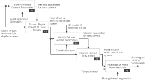
Figure 1: Overview of our proposed system.
298 Endo and Hayashi
SYSTEM OVERVIEW
Figure 1 shows an overview of the proposed system. The system consisted of five steps. First, the intrinsic parameters of each depth camera were identified. Multiple IR images were obtained by changing the position and orientation of the checkerboard and were used to identify the transformation matrix from the two-dimensional coordinate system of the depth image to the 3D camera coordinate system and lens distortion correction parameters. The methods for acquiring the intrinsic parameters (A1) and generating point clouds from depth images using these parameters (A2) are not described in detail in this study because we used the method proposed by Zhang et al., (2000) as these processes. Second, the extrinsic parameters of each depth camera were identified, which represent the position and orientation of each camera in the world coordinate system as a homogeneous transformation matrix (A3). Using these parameters, a point cloud was obtained for the body shape of a person using the world coordinate system (A4). Third, a nonrigid mesh reg- istration method was used to deform the template mesh of the human body to obtain a homologous mesh of the person (A5).
IDENTIFYING EXTRINSIC CAMERA PARAMETERS The extrinsic camera parameters (i.e., position and orientation) of each depth camera were estimated by the following steps:
1) Making a digital model of a reference object as a 3D polygon mesh; 2) Making a physical model with the same geometry as the digital model, which was created using a 3D printer; 3) Capturing a part of the physical model with each depth camera to obtain a point cloud in the camera coordinate system; and 4) Identifying a homogeneous transformation matrix for each camera to fit the obtained point cloud to the digital model.
The detailed steps are as follows.
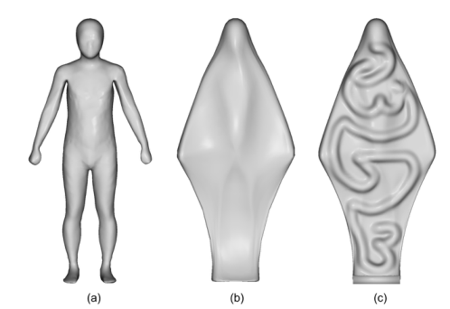
Figure 2: Construction process of a polygon mesh model for the reference object. (a) An average body shape of Japanese adult males, (b) a smoothed shape for the convex hull of (a), (c) a shape with manually painted embossments on the surface of (b).
iBODY: Human Body Shape Reconstruction by Using Multiple Depth Cameras 299
Making Digital Model of Reference Object A digital model of the reference object must be created as a polygon mesh because it is used to create its physical model using a 3D printer in the next step. The requirements for the reference object are defined as follows:
The shape should be as similar as possible to the shape of the human body during the measurement. The subject’s posture at measurement was assumed to be the A-pose (in an upright position, arms open at an angle, and palms facing inward).
An object’s physical model must be created using a 3D printer. To reduce the time and cost of modeling, it is preferable to omit the limbs.
The shape must be formed so that the position and orientation of each camera could be uniquely identified. Therefore, the shape did not contain planar, spherical, or axisymmetric parts.
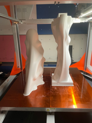
Figure 3: Construction of a physical model for the reference object by using a 3D printer.
Figure 2 shows the construction process of a polygon mesh model for the reference object. First, we created a polygon mesh with the average body shape of adult Japanese males by referring to the 3D human body shape database (HQL 2006) (see Figure 2[a]). Therefore, this shape looks similar to the shape of the human body and is appropriate as a reference object. However, building such a complicated shape with a 3D printer requires con- siderable time and cost because it needs to be divided into many parts and requires a large amount of support material. Therefore, as Figure 2(b) shows, the next step was to create a convex hull of the human body shape, which was then smoothed using the Laplacian mesh smoothing method (Sorkine et al., 2004). This shape has few undulations, which makes it difficult to uniquely identify the camera’s location; therefore, we manually added embossments to the surface of this mesh (see Figure 2[c]).
300 Endo and Hayashi
Making Physical Model of Reference Object The next step was to create a physical model of the reference object using a 3D printer with the same geometry as its digital model. We used a BigRep ONE.4 (BigRep GmbH 2023), a 3D printer capable of creating physical objects up to 1 m apart. The dimensions of our proposed reference object were 750 [mm] (width) × 1,700 [mm] (height) × 300 [mm] (depth); therefore, as Figure 3 shows, the physical model was created by dividing it into two parts in the height direction.
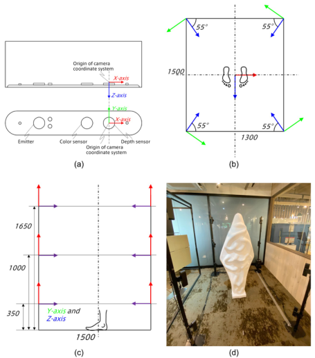
Figure 4: Placement of multiple depth cameras. (a) Origin of camera coordinate sys- tem, (b) and (c) global position and orientation of each camera (top and side views respectively). Arrows at the center position in (b) show the world coordinate system and other arrows show the camera coordinate system of each camera. (d) Placement of the reference object in the global calibration process. All dimensions in the figures are in millimeters.
Capturing Reference Object To measure a human body with as few defects as possible, depth cameras should be positioned so that all areas of the reference object were measured. Astra S (Orbbec), the depth camera used in our experiments, had 60
hor- izontal and 49.5
vertical fields of view. Based on several experiments, we decided to place 12 cameras around the measurement area (see Figure 4). After placing the reference object at the center position, its shape was cap- tured by these cameras, and a point cloud was obtained from each depth image. To suppress the effects of errors in the intrinsic camera parameters, points at distances greater than τc from the origin of the camera coordinate system were removed.
iBODY: Human Body Shape Reconstruction by Using Multiple Depth Cameras 301
Identifying Position and Orientation of Each Depth Camera As described in previous sections, the position and orientation of each depth camera were represented as a homogeneous transformation matrix, which was identified as follows:
1. A dense point-cloud PR was generated on the mesh surface of the reference object. 2. For each point p in point cloud Pc obtained from each depth camera c, we determined the nearest point qp ∈PR. If distance between p and qp was less than a user-defined tolerance τd, the pair {p, qp} was appended to a set S. 3. Find a homogeneous transformation matrix Tc for each camera c, by solving the optimization problem min ←P {p,qp}∈S
qp −Tcpc 2. Where pc was the position vector of p in the camera coordinate sys- tem 6c, and qp was the position vector of qp in the world coordinate system 6W. This problem could be solved using a closed-form solution (Berthold et al., 1988). 4. Repeat Steps 2 and 3 for user-defined number of times n.
CAPTURE OF HUMAN BODY SHAPE The subject’s body shape was captured as a set of point clouds using the multiple-depth camera setup described above. As with the global calibra- tion, the points farther than τc were removed. In addition, the measurement error of the depth camera increased as the angle between its direction and the measured surface approached 0
. Therefore, the points which satisfied the following equation were removed: (−vc) · np < cos τr, where vc was a unit vector of the centerline (from the viewpoint to the gaze point) of the camera, np was the normal vector of the point p, and τr was a user- defined tolerance of the angle. Here, np was estimated as the eigenvector corresponding to the smallest eigenvalue obtained by principal component analysis for the position of the points around p. Both vc and np were represented in 6c.
The position vector p in 6W of each point p could be obtained as p = Tcpc. Each point cloud was merged into a point cloud P in 6W which contained the whole-body shape of the subject.
RECONSTRUCTING HOMOLOGOUS MESH MODEL Finally, a homologous polygon mesh M was obtained by deforming the tem- plate mesh M0 to fit M0 to the obtained point cloud P. For M0, we used a mesh with the average body shape of adult Japanese males (see Figure 2[a]). We used a nonrigid mesh registration method (Yamazaki et al. 2013) for the mesh deformation from M0 to M. This algorithm was robust against defects such as incomplete body parts and the presence of background objects and was capable of generating a high-resolution mesh model without large geometric distortion.
302 Endo and Hayashi
RESULTS
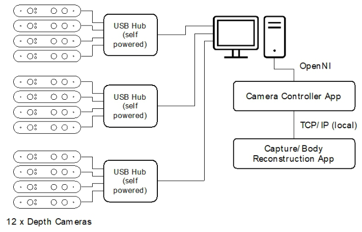
Figure 5 shows the hardware and software configurations of the proposed system. The system was implemented as an additional package of a plat- form software for human models called DhaibaWorks (Endo et al., 2023). To provide a stable power supply for the 12 depth cameras, each camera was connected to a computer via three self-powered USB hubs to provide a stable power supply. We developed two programs: one for controlling the cameras via OpenNI, and the other for processing the capture and body reconstruc- tion. These two programs were connected via TCP/IP, with the latter sending commands to the former to obtain the point clouds from each camera. In this case, all cameras were connected to a single computer; therefore, it was possible to merge these two programs and configure them to access the cam- eras without TCP/IP. However, the configuration in Figure 5 allowed camera controllers to be distributed across several different computers, making it possible to measure a large area or use more cameras than one computer could handle.
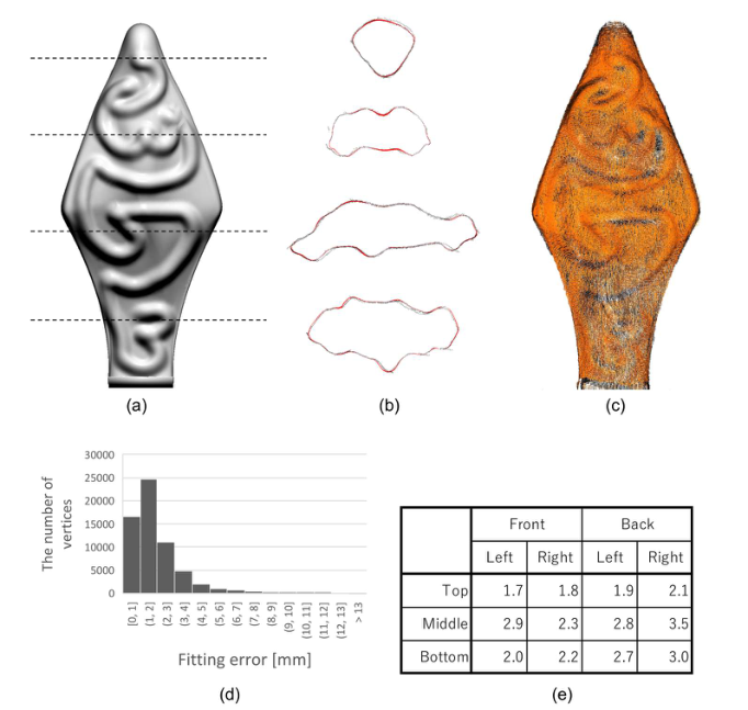
Figure 6 shows the results of the proposed global calibration method. The user-defined parameters were set as follows: τc = 1, 200 [mm], τd = 50 [mm], n = 200. The mean and standard deviation of the error of the obtained point cloud relative to the mesh for the reference object were 2.0 [mm] and 1.8 [mm] respectively. As Figure 6 (b) shows in the cross-sectional view, the obtained point clouds appropriately fit the reference object’s shape, indicating that the position and orientation of each camera were estimated accurately. From a quantitative perspective, it was confirmed that the mean fitting errors concerning the cameras were all less than 0.5% (see Figure 6[e]).
Figure 5: Hardware and software configuration of our proposed system.
iBODY: Human Body Shape Reconstruction by Using Multiple Depth Cameras 303
Figure 6: Results of our proposed global calibration method. (a) Polygon mesh of the reference model and height of each cross section and (b) several cross-sectional views. Red lines show the polygon mesh and black points show obtained point cloud. (c) Obtained point clouds, (d) fitting error distribution of the obtained point clouds rel- ative to the mesh for the reference object and (e) mean fitting error [mm] of the point cloud for each camera.
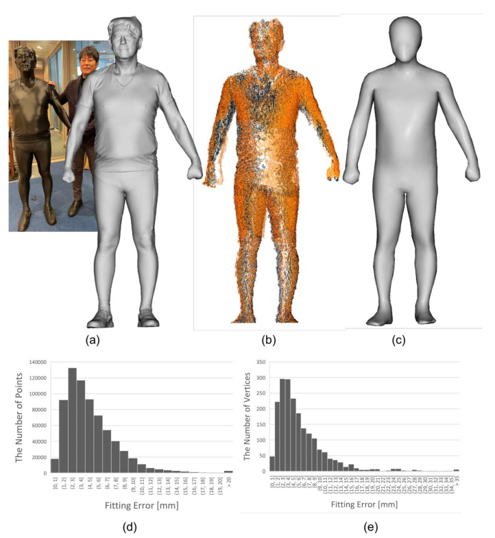
Figure 7 shows the results of the body scan and mesh reconstruction pro- cesses. To reveal the error distribution in the measured point cloud and reconstructed homologous mesh model, we measured a subject’s body shape using a high-precision handheld scanner (Artec 3D 2012) to create a poly- gon mesh and then created a physical mockup by 3D printing (Figure 7[a]). We determined τr as 50
. The mean and standard deviation of the error of the point cloud obtained relative to the mesh for the subject were 4.7 [mm] and 3.3 [mm] respectively. By contrast, the mean and standard deviation of the fitting error of the vertices in the reconstructed homologous mesh rela- tive to the mesh for the subject were 6.1 [mm] and 5.3 [mm], respectively. To reduce the time required for deformation, we created a homologous mesh for the subjects using a template mesh with only 3,998 faces. Nevertheless, the mean fitting error was less than 0.3%, relative to the height of the subject, confirming that the proposed method created high-precision homologous meshes.
304 Endo and Hayashi
Figure 7: Results of the body scan and mesh reconstruction process. (a) A polygon mesh of a subject measured with a handheld scanner and its physical mockup created with a 3D printer, (b) a point cloud obtained by measuring the physical mockup of (a) with our proposed body scan system, (c) a homologous mesh reconstructed from (b), (d) fitting error distribution of the points in (b) relative to the mesh in (a) and (e) fitting error distribution of the vertices in (c) relative to the mesh in (a).
CONCLUSION
In this study, we proposed a new 3D body-shape measurement method using multiple depth cameras. A reference object for global calibration with a human-like shape suitable for 3D printing was proposed. Furthermore, we applied a nonrigid mesh registration method to a template human model to reconstruct a homologous polygon mesh using a high-density point cloud obtained from the human body surface. It was confirmed that the fitting error of the reconstructed homologous mesh relative to the measured body shape was sufficiently small.
iBODY: Human Body Shape Reconstruction by Using Multiple Depth Cameras 305
ACKNOWLEDGMENTS
This work was supported by JSPS KAKENHI Grant Number JP21H03525.
REFERENCES
Artec 3D (2012), Artec Eva, viewed 26 July 2023, < https://www.artec3d.com/ portable-3d-scanners/artec-eva> Berthold K. P. Horn, Hugh M. Hilden, and Shahriar Negahdaripour (1988), “Closed-
form solution of absolute orientation using orthonormal matrices”, Journal of the Optical Society of America A Volume 5, Number 7, pp. 1127–1135. BigRep GmbH (2023), BigRep ONE.4, BigRep GmbH, viewed 22 July 2023, <https://bigrep.com/ja/bigrep-one> Endo, Y., Maruyama, T., Tada, M. (2023), “DhaibaWorks: A Software Platform for
Human-Centered Cyber-Physical Systems”, International Journal of Automation Technology Volume 17, Number 3, pp. 292–304. HQL (2006), Database of Japanese human body dimensions 2004-2006, Research Institute of Human Engineering for Quality Life (HQL) Kilner, J., Neophytou, A., Hilton, A. (2012), “3D Scanning with Multiple Depth
Sensors”, Proceedings of 3rd International Conference on 3D Body Scanning Technologies. pp. 295–301. Mulla, O., Grunnet-Jepse, A. (2021), “Multi-Camera configurations with the Intel RealSense LiDAR Camera L515”, Intel, viewed 26 July 2023, <https://dev.intelrealsense.com/docs/lidar-camera-l515-multi-camera-setup> Orbbec, Astra S, viewed 23 July 2023, <https://shop.orbbec3d.com/Astra-S> Sorkine, O., Cohen-Or, D., Lipman, Y., Alexa, M., Rössl, C., Seidel, H.-P.
(2004), “Laplacian Surface Editing”, Proceedings of the 2004 Eurographics/ACM SIGGRAPH Symposium on Geometry Processing. SGP ‘04. pp. 175–184. Wu, G., Li, D., Zhong, Y., Hu, P. (2017), “A study on improving the calibration of body scanner built on multiple RGB-Depth cameras”, International Journal of Clothing Science and Technology Volume 29, Number 3, pp. 314–329. Yamazaki, S., Kouchi, M., Mochimaru, M. (2013), “Markerless landmark local-
ization on body shape scans by non-rigid model fitting”, Proceedings of 2nd international digital human modeling symposium 2013. Zhang, Z. (2000), “A flexible new technique for camera calibration”, IEEE Transactions on Pattern Analysis and Machine Intelligence Volume 22, Number 11, pp. 1330–1334.
LISTED IN THE AHFE DIGITAL BOOKSTORE CATALOGUE
Explore the complete digital volume
Human-Centered Design and User Experience
Read this individual research paper free through the original publisher, or explore the full digital proceedings book.
ISBN 978-1-958651-90-2
Explore this ISBN in the AHFE Bookstore ↗Listed in the July 2026 bookstore catalogue; search by ISBN to confirm current availability · Digital book purchase optional