Shigeaki Futagami, Kimi Ueda, Hirotake Ishii, Hiroshi Shimoda (2024). 3D Reconstruction Method Using A Pendulum RGB-D Camera. In: Intelligent Human Systems Integration (IHSI 2024): Integrating People and Intelligent Systems. AHFE Open Access, vol. 119, pp. 341–347. https://doi.org/10.54941/ahfe1004498
3D models are used in various fields to reproduce the real environment in a virtual world, such as assessing conditions at construction sites, sharing blueprints and other data, and disaster experiences using Virtual Reality. Various methods have been developed to create 3D models of real environments, including methods using laser scanners and cameras. The method using a laser scanner can create an accurate 3D model, but the equipment is expensive and not easy to use. On the other hand, the method of using a camera is less accurate than a laser scanner, but it is less expensive and easier to use. In the camera-based method, the pose, which encompasses the 3D coordinates of the camera and its orientation at the moment the image was acquired, is estimated through image processing. Then, a 3D model can be created based on the estimated camera poses. In this method, it is difficult to estimate the camera poses from images with few image features. Therefore, in regions with few features, such as flat walls of a single color, it is difficult to reconstruct the 3D model.In this study, camera poses are estimated using the camera moving as a pendulum and using these poses to create a 3D model. The camera is attached at the end of a pendulum so that the camera motion can be physically modeled, and the trajectory of the camera can be accurately estimated. In this method, the environment is first photographed using a pendulum camera in which an RGB-D camera is used for the weight of the pendulum. Then, tracking is performed to estimate the part of the pendulum motion using clear images that represents the area with enough features. Next, the fulcrum position and length of the pendulum are estimated using the tracking results. The fulcrum position and the length are then used to estimate the camera poses for all images by the pendulum physical model. Finally, the camera poses are used to perform a 3D reconstruction of the captured environment. To evaluate the effectiveness of this method, the 3D models created with and without the proposed method were compared from two perspectives: the size of the area that could be reconstructed and the accuracy of the 3D models created. As a result, the proposed method was able to reconstruct the 3D model even in regions where enough features cannot be obtained from the images. However, the model created with the proposed method displays the subject shifted from frame to frame compared to the model created without the proposed method. This is supposed to be due to the fact that the calculated camera poses were not accurate enough because the estimated length of the pendulum included an error. Future work is needed to further improve the accuracy of the camera pose estimation in order to improve the accuracy of the model. Other possibilities include extending the shooting range by conducting cooperative photography with multiple cameras.
3D models are used in various fields to reproduce the real environment in a virtual world, such as assessing conditions at construction sites, and disaster experiences using Virtual Reality (Wataru Asaba et al. 2023). Various meth- ods have been developed to create 3D models of real environments. These methods include the use of laser scanners (Rui Wang. 2021), RGB cameras (Johannes Schönberger et al. 2016), and RGB-D cameras (Yuki Harazono et al. 2022). The method using a laser scanner can create an accurate 3D model, but the equipment is expensive and not easy to use. On the other hand, methods using cameras are less expensive and easier to use than meth- ods using laser scanners. Method using cameras estimates the position and orientation of the camera at the time when the image was taken by processing the image (hereinafter referred to as “camera pose”together with the position and orientation of the camera), and creates 3D models using the estimated camera pose. However, it is difficult to estimate the camera poses for images with few features. Regions with few features, such as flat walls of a single color, cannot be reconstructed and fall out of the 3D model.
To solve this problem, in this study, camera poses are estimated using the camera motion moving as a pendulum and using the estimated poses to create
a 3D model. The pendulum motion is determined by the laws of motion, and the full trajectory of the camera can be estimated from part of the pendulum motion.
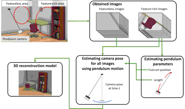
PROPOSED METHOD The conceptual diagram of the proposed 3D reconstruction method using a pendulum motion camera (hereinafter referred to as “pendulum camera”) is shown in Figure 1. The proposed method uses an RGB-D camera that can capture both color and depth images. For this study, the camera is not sus- pended by a string but by a thin pole, so that the camera oscillates in the same direction on a single plane. This facilitates the estimation of the camera pose.
When capturing images of the environment, the camera oscillates several times and the images and the exact time when the images were taken are stored. The process flow after the image is taken is divided into four steps.
In Step 1, tracking is performed to estimate the motion of the pendulum camera from the acquired image. At this time, if there are too few feature points recognized on the images used for tracking, tracking cannot be per- formed correctly, and therefore, there must be enough feature points on the images. Therefore, as in Step 1-1, feature points are recognized using image processing for all images, and only images containing a predetermined num- ber of feature points are extracted. Then, in Step 1-2, tracking is performed using only the images extracted in Step 1-1.
Figure 1: Conceptual diagram of the proposed method.
In Step 2-1, first, the plane in which the pendulum moves is estimated using the camera position obtained by the tracking, and the camera position is projected onto this plane. In the proposed method, it is assumed that the pendulum camera hardly moves in the direction the camera is facing because the hardware is designed to move on a single plane. On the other hand, the
A 3D Reconstruction Method Using a Pendulum RGB-D Camera 343
camera position obtained by image-based tracking includes an error in this direction, so the error effect can be suppressed by estimating the plane of motion and projecting onto that plane. The proposed method estimates the plane using the RANSAC algorithm (Rahul Raguram et al. 2013). Then, in Step 2-2, the fulcrum position and length of the pendulum camera are esti- mated using the RANSAC algorithm as in Step 2-1. In this step, the camera positions excluding the outliers from the plane estimation are used to elim- inate the influence of outliers in the estimation. In Step 2-3, the fulcrum position and length of the pendulum camera estimated in Step 2–2 are opti- mized using the camera positions to improve the estimation accuracy. The camera positions that are outliers in Step 2–2 are not used because they cause a decrease in estimation accuracy. The steepest descent method is used as the optimization method.
In Step 3-1, the camera position is projected onto the motion trajectory of the pendulum, which is estimated from the fulcrum position and length of the pendulum camera obtained in Step 2. In the proposed method, since the camera is suspended from a pillar that can be regarded as a rigid body, the motion trajectory of the pendulum is considered to be the same regardless of the number of vibrations, except for damping. Therefore, by projecting the camera position on the estimated motion trajectory of the pendulum, the tracking error is reduced and the projected camera position is expected to be closer to the actual camera position when the image was taken. Then, in Step 3-2, the camera pose of all images is estimated using the time the images are acquired, the angle when the pendulum camera starts moving, the estimated fulcrum position, and the lengths of the pendulum camera. By solving the equation of motion numerically, the angle formed by the pendulum can be accurately determined from the elapsed time after the start of moving.
In Step 4, a 3D point cloud model is obtained by 3D reconstruction using color images, depth images, and the camera pose estimated through Step 1 to 3.
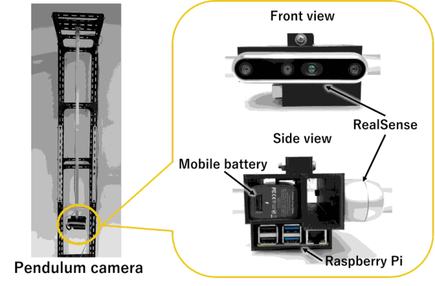
HARDWARE The pendulum camera used in the proposed method consists of a platform to support the whole system, a pillar to hang the camera, an RGB-D camera (Intel RealSense D455) to capture the environment, a single board computer (Raspberry PI 4B) to control the RGB-D camera, and a battery to drive them. Figure 2 shows the prototype pendulum camera. The pillar of the pendulum was made of square pipe so that it would not flex. The RGB-D camera, single- board computer, and battery are fixed to the end of the pendulum prop. The radius of the pendulum was about 1.3 m and the weight of the tip of the pendulum camera was 378 g.
EVALUATION OF THE PROPOSED METHOD Evaluation Objective and Method
A prototype of the proposed method was built as an actual device and its performance was evaluated. The purpose of this evaluation is to assess the
effectiveness of the proposed 3D reconstruction method in terms of the area that can be reconstructed and the accuracy of the 3D model created. In this evaluation, the effectiveness of the method was assessed using 3D point cloud models obtained from the case in which 3D reconstruction is performed using only the results of tracking using acquired images (Pattern 1) and the case in which 3D reconstruction is performed using all acquired images by applying the proposed method (Pattern 2).
Figure 2: The prototype pendulum camera.
Results and Discussion
433 pairs of images (six round trips) were used in this evaluation. The number of color and depth image pairs used for the 3D reconstruction is 121 for Pattern 1 and 433 for Pattern 2. In Pattern 1, only about 28% of all image pairs were used for 3D reconstruction excluding those for which camera pose tracking was unfeasible due to the insufficient number of feature points.
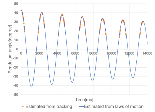
Figure 3 shows the pendulum angle. The orange dots are the pendulum angle obtained by operations up to Step 3-1, and the blue line is the result estimated by solving the equations of motion numerically. The horizontal axis is the time elapsed since the start of the motion, and the vertical axis is the pendulum angle. Figure 3 shows that the proposed method can reproduce the entire motion of a pendulum even when only a part of its motion trajectory is known. This enables us to estimate the pendulum angle even for the part where the pendulum angle could not be obtained by image processing, and this angle can be used to determine the camera pose.
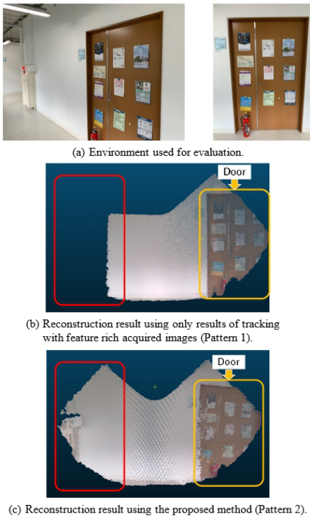
The reconstruction results for the two patterns are shown in Figure 4. (a) shows the environment used in this evaluation. Also shown in (b) is the reconstruction result for Pattern 1 and (c) is the reconstruction result for Pattern 2.
A 3D Reconstruction Method Using a Pendulum RGB-D Camera 345
Figure 3: The pendulum angle determined by tracking (ORANGE) and the trajectory of the pendulum angle estimated using the laws of motion (BLUE).Figure 4: Environment and results of 3D reconstruction.
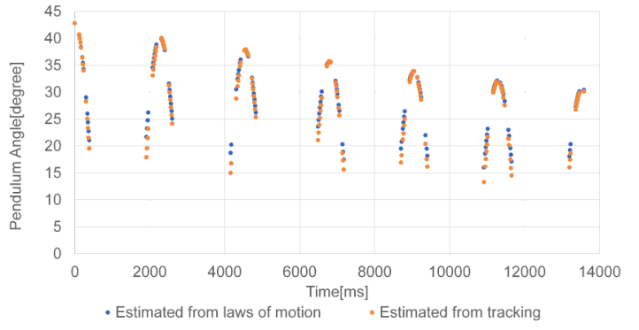
Comparing Pattern 2 with Pattern 1, it can be seen that a wider area than in Pattern 1 was reconstructed for the areas indicated by the red square in (c). These results show that the proposed method can be used to reconstruct 3D images of regions with few features and that the use of such images enables 3D reconstruction of regions that could not be reconstructed using methods that only rely on environmental features. However, the 3D model of Pattern 2 was less accurate than in Pattern 1. The yellow area which shows the door and many posters was visible in Pattern 1 but a little blurred in Pattern 2. And the door is slightly tilted against the ground. This is thought to be because the estimated camera pose is different from the actual one. The possible rea- son is that the estimation of the fulcrum position and length of the pendulum contains errors. Since the RANSAC algorithm is used to determine the ful- crum position and length of the pendulum, a certain amount of error may be included. Although optimization is then performed to reduce the effect of the error as much as possible, the error still cannot be completely eliminated, and this is thought to affect the estimation of the camera attitude as well. Figure 5 shows the angle of the pendulum obtained by tracking, and estimated values using the laws of motion at the same time. Figure 5 shows that as the pen- dulum camera moves away from the starting point, the differences between the results estimated by the equation of motion and the results estimated by tracking become larger. This difference may have been caused by inaccurate estimation of the radius of the pendulum, which led to inaccurate estimation by the equation of motion.
Figure 5: Angle of the pendulum obtained by tracking (ORANGE) and estimated value using the laws of motion at the same time (BLUE).
CONCLUSION
In this study, we proposed a method of 3D environment reconstruction using a pendulum camera and developed a system using this method. The effectiveness of the proposed method was evaluated by comparing it with the case in which only the results of image-based tracking were used.
A 3D Reconstruction Method Using a Pendulum RGB-D Camera 347
The 3D model created by the proposed method had a wider recon- structable area than that created by only tracking using images, and it was confirmed that the 3D model could be reconstructed even in an area with few feature points. However, the accuracy of the 3D model created by the proposed method was lower than that of tracking alone. This is thought to be because the estimated camera pose is different from the actual one.
Future works include improving the accuracy of the estimated camera poses used for 3D reconstruction. Another is to use a string instead of a thick rigid body to suspend the camera so that it can take pictures at various rotation radii to allow easy installation in various locations.
ACKNOWLEDGMENT
This work was supported by JSPS KAKENHI Grant Number 23K11166.
REFERENCES
Johannes L. Schönberger, and Jan-Michael Frahm. (2016). “Structure-from-Motion Revisited”, IEEE Conference on Computer Vision and Pattern Recognitio, pp. 4104–4113. Johannes L. Schönberger, Enliang Zheng, Jan-Michael Frahm and Marc Pollefeys.
(2016). “Pixelwise View Selection for Unstructured Multi-View Stereo”, European Conference on Computer Vision, pp. 501-518. Rahul Raguram, Ondrej Chum, Marc Pollefeys, Jiri Matas, and Jan-Michael Frahm.
(2013). “Usac: A universal framework for random sample consensus”, IEEE Transactions on Pattern Analysis and Machine Intelligence, Vol. 35, No. 8, pp. 2022–2038. Rui Wang. (2021). “3D Reconstruction Using a Linear Laser Scanner and A Camera” 2nd International Conference on Artificial Intelligence and Computer Engineering (ICAICE), pp. 666–672. Wataru Asaba, Kimi Ueda, Hirotake Ishii, and Hiroshi Shimoda. (2023) “Evaluation
of the Effect of VR Disaster Experience in Familiar Environment”, Intelligence Human Systems Integration, Vol. 69, pp. 667–676. Yuki Harazono, Hirotake Ishii, Hiroshi Shimoda, Yasuyoshi Taruta, and Yuya Kouda. (2022). “Development of AR-based scanning support system for 3D model reconstruction of work sites”, Journal of Nuclear Science and Technology, Vol. 59, No. 7, pp. 934–948.
LISTED IN THE AHFE DIGITAL BOOKSTORE CATALOGUE
Explore the complete digital volume
Intelligent Human Systems Integration (IHSI 2024): Integrating People and Intelligent Systems
Read this individual research paper free through the original publisher, or explore the full digital proceedings book.
ISBN 978-1-958651-95-7
Explore this ISBN in the AHFE Bookstore ↗Listed in the July 2026 bookstore catalogue; search by ISBN to confirm current availability · Digital book purchase optional