Alexander Ackermann, Thomas Jaitner, Sascha Wischniewski (2024). Validation of a 3D body scanner system with automated circumference measurement calculation while considering the influence of different 3D data types. In: Accessibility, Assistive Technology and Digital Environments. AHFE Open Access, vol. 121, pp. 239–249. https://doi.org/10.54941/ahfe1004633
Anthropometry is crucial in ergonomic designing to ensure accommodation of diverse body sizes and shapes. 3D body scanning systems are now widely employed in anthropometric surveys for collecting data, requiring validation according to ISO 20685-1 for ISO 7250-1 measurements. The aim of this study was to assess the validity of the 3D body scanning system, Vitus Bodyscan, in combination with Anthroscan, for automatically calculated circumference measurements specified in ISO 7250-1, while considering the influence of different 3D data types. Overall, 9 circumference measurements were collected from 44 adult subjects. For the manual measurement, ISO 7250-1 guidelines were considered. For the 3D scanning, each participant was scanned once in a standing posture. Thereafter, proprietary Anthroscan algorithms were used to generate a watertight mesh from the initial 3D point cloud and computed the circumference measurements automatically. With the exception of calf circumference, scan-derived measurements exceeded the acceptable error margins specified in ISO 20685-1 and were therefore not comparable to manual measurements due to several possible factors. Practitioners need to consider these variations when using the scan-derived values. Looking at the differences between scan-derived measurements based on point clouds or watertight meshes, the deviations were negligible for most circumference measurements, except for arm circumference with better results based on point clouds. For simplicity, the authors recommend the use of point clouds for all circumference measurements studied. However, the recommendations are based on the anthropometric measurements and the 3D body scanning system used in this study and cannot be generalized.
a defined target population (Pheasant and Haslegrave, 2006). For instance, anthropometric measurements are needed for appropriately scaling digital human models (DHM) in order to obtain meaningful results in a virtual ergonomic design or evaluation process employing such DHM (Chaffin, 2005). ISO 7250–1 (ISO, 2017) outlines basic anthropometric measurements for technological design and provides standardized procedures for their col- lection with the manual measuring method using various anthropometric instruments (e.g. anthropometer, calipers, or measuring tape). In general, anthropometric measurements can be divided into different measurement types such as height, depth, breadth, length, and circumference measure- ments. All of these measurement types can be relevant in an ergonomic design process. For example, different height, depth, width, and length measure- ments are relevant for the design of a seated office workstation (Gordon, 2002). Some circumference measurements of the limbs and torso are required for the design of exoskeletons or fall-arrest harnesses (Hsiao, 2013; Riemer and Wischniewski, 2022).
Nowadays, due to technological advances, 3D body scanning systems are increasingly used in anthropometric surveys to collect this kind of data (see for example “Size Korea”: Kim, You and Kim, 2017). Initially, 3D scanners produce a 3D point cloud representing the subject’s body surface, which can be used as a data basis to construct a so-called watertight mesh using different types of algorithms. A watertight mesh is a closed collection of connected polygons representing the body surface. Technically, it is possible to compute all types anthropometric measurements from a mesh or a point cloud.
In general, ISO 20685–1 (ISO, 2018) stipulates a validation study to assess the comparability between a specified 3D body scanning system and the manual measuring method (i.e. the gold standard method according to ISO 7250-1) and provides some basic guidelines for the study design along with defined acceptable error margins for the different types of anthropometric measurements. Over the last two decades, numerous validation studies have been conducted to validate the hardware and software components of vari- ous 3D body scanning systems (Han, Nam and Choi, 2010; Kuehnapfel et al., 2016; Glock et al., 2017; Tiwari and Anand, 2022). Summarizing the results, differences between the measuring methods exceeded the acceptable error margins of ISO 20685–1 in most of the cases.
In this study the Vitus Bodyscan (VITRONIC, Wiesbaden, Germany) combined with the Anthroscan software (version 3.6.1, Human Solutions, Kaiserslautern, Germany) was used. Anthroscan incorporates many features, such as an algorithm for creating watertight meshes, and facilitates the fully automated calculation of various anthropometric measurements, including several circumference measurements also mentioned in ISO 7250-1. Valida- tion of this 3D whole-body scanning system and the associated algorithms is necessary because this system is available in the laboratories of the Federal Institute for Occupational Safety and Health (BAuA) in Dortmund, Germany, and will be used to collect anthropometric data for ergonomic designing and in future also by other institutions.
Hence, the aim of this current study was to evaluate the 3D body scan- ning system, Vitus Bodyscan in combination with Anthroscan, according to
Validation of a 3D Body Scanner System 241
ISO 20685–1 for the valid collection of the automatically calculated circum- ference measurements mentioned in ISO 7250-1. In particular, the authors evaluated how the use of the proprietary Anthroscan algorithm to generate watertight meshes affected the performance of the measurement calculation algorithm. Validation of height, depth, width, and length measurements from ISO 7250–1 is covered separately in another research article, as the data collection and analysis procedure for scan-derived measurements was considerably different for these types of measurements.
METHODS
Participants Overall, 44 adult subjects (24 women, 20 men) with diverse body sizes and shapes participated in this study. Additional details about the study sample are provided in Table 1. Eligible participants were required to be within the working age range (18-67 years) and have sufficient language skills to understand the study information letter in German. Exclusion crite- ria included individuals with acute body swelling or non-removable bandages and pregnant women, as these could introduce a bias into the 3D scan results. Participants who reported an inability to sit or stand upright for at least 15 seconds were also excluded. The study was approved by the local ethics com- mittee of BAuA (approval number: 048_2021) and written informed consent was obtained from all participants prior to enrollment in accordance with the principles of the Declaration of Helsinki.
Table 1. Sample characterization.
Table available in the original PDF paper.
Variable Females Males Total Number of participants [n] 24 20 44 Age [years] mean ± SD 36.8 ± 15.7 34.8 ± 11.9 35.9 ± 14.0 min–max 18–67 20–59 18–67 Body mass [kg]* mean ± SD 65.2 ± 11.8 85.0 ± 16.1 74.2 ± 17.0 min–max 47–95 55–128 47–128 Stature [mm]** mean ± SD 1673 ± 77 1831 ± 85 1745 ± 113 min–max 1529–1815 1625–1935 1529–1935
Data Collection A single trained examiner (E1) conducted all parts of the study to avoid possible examiner effects and was supported by a single assistant examiner (E2). The training phase, which lasted three months with approximately three weekly sessions of four to five hours each, included all circumfer- ence measurements examined in this study as well as other anthropometric measurements from ISO 7250-1. Due to the academic background, E1 already had basic knowledge at the beginning. In general, the training phase incorporated theoretical sessions on anthropometry, anthropometric mea- surements, the manual measuring method, and 3D body scanning, utilizing
a measurer’s handbook and various training materials such as scientific lit- erature, international standards (e.g. ISO 20685–1 & 7250-1), and publicly available ANSUR resources. Practical training involved supervised sessions (approx. 20 hours) and ordinary measuring sessions (approx. 100 hours) using individuals with diverse body types.
Standard operating procedures were established to enhance the degree of standardization within the entire data collection procedure. Once par- ticipants signed the informed consent and data use agreement, a question- naire was used to collect some demographic data. Then, the collection of anthropometric data started. A total of 9 circumference measurements from ISO 7250-1 were obtained using the manual measuring method and the 3D body scanning system (see Table 2). Following ISO 20685–1 guidelines, par- ticipants wore close-fitting short underwear (and a bathing cap for the body scanning procedure) for these parts of the study.
For the manual measuring method, anthropometric data were collected using a tape measure (Lufkin, United States) following the prescribed pro- tocols of IS0 7250-1. Hip circumference, a versatile circumference mea- surement not defined in ISO 7250-1, was recorded according to ANSUR II (Hotzman et al., 2011, section 6.4.17). E2 checked that participants main- tained an appropriate posture and controlled the alignment of the anthro- pometric instrument (e.g. horizontal level of the tape measure). Once E1 obtained the measurement value, it was verbally reported to E2. In cases of noticeably irregular values, E1 repeated the measurement process.
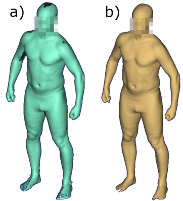
In a next step, the Vitus Bodyscan was utilized to acquire 3D body scans of the subjects. This 3D full-body laser scanner provides a measurement volume of 210 × 120 x 120 centimeters (height x width x depth) and a resolution of approximately 300 points per cm3 with a scanning time of less than 10 sec- onds. The 3D scanner was calibrated on a daily basis. For the current study, each participant was scanned once in a standing position as recommended by Anthroscan, hereafter referred to as the standard posture (see Figure 1). A more detailed description of the posture can be found in the study of Bonin et al. (2022, Table 2) and the Anthroscan manual. E1 provided guid- ance to participants and carried out the scanning procedure. After each scan, E1 and E2 inspected the generated 3D body scan to verify the correct body posture and overall scan quality. If required, the scan procedure was repeated. The study was then completed for the subjects.
Validation of a 3D Body Scanner System 243
The 3D body scan that is initially generated within the scanning process corresponds to a 3D point cloud (see Figure 1a). However, as already stated, this study also aimed to investigate the influence of different data types on the comparability of the two measuring methods. Thus, algorithms implemented in Anthroscan were employed. First, Anthroscan was used to determine a watertight mesh for each subject (see Figure 1b) based on the existing 3D point cloud. Thereafter, Anthroscan was used to automatically calculate the 9 circumference measurements for each subject based on the 3D point cloud and the watertight mesh.
Figure 1: Body posture during the 3D scanning process with a) illustrating the initially generated 3D point cloud and b) the watertight mesh.
Data Analysis For data analysis, the following anthropometric data were available for each of the 44 subjects:
One value for each of the 9 manually collected circumference measure- ments.
One value for each of the 9 automatically calculated scan-derived circum- ference measurements obtained from 3D point clouds.
One value for each of the 9 automatically calculated scan-derived circum- ference measurements obtained from 3D watertight meshes.
Initially, the difference between scan-derived measurements and their corresponding manually measured counterparts was computed. Following established practices from other validation studies (Han, Nam and Choi, 2010; Bragança et al., 2017; Tiwari and Anand, 2022), an outlier anal- ysis was conducted to remove abnormal data, excluding values smaller or greater than the mean difference plus/minus three standard deviations. The remaining data were processed according to ISO 20685–1 (section 5), enabling an evaluation of the comparability between manual measurements and scan-derived measurements from different data types. In summary, a 95% confidence interval (CI) is defined using the calculated difference values, followed by an assessment of the CI boundary values to determine if they fall
within the acceptable error margins specified in ISO 20685-1. The accept- able error margins are 4 mm for small circumferences and 9 mm for large circumferences. If the CI boundary values fall within these error margins, scan-derived values are comparable with manually measured values accord- ing to ISO 20685-1. For a more in-depth analysis, Bland Altman (BA) plots were computed using the mean difference and standard deviation to define the limits of agreement (mean ± 1.96*standard deviation).
RESULTS
Results of the ISO 20685–1 analysis are shown in Table 3 (scan-derived based on point cloud vs. manual) and Table 4 (scan-derived based on watertight mesh vs. manual). As can be seen from these tables, only the scan-derived values for calf circumference are within the acceptable error margins specified in ISO 20685-1. For clarity, the constructed BA plots are illustrated in the appendix.
Table 3. Comparison of manual measurement values and scan-derived measurement values based on point clouds according to IS0 20685–1 (computation: scan- derived minus manual values).
N = number of subjects, SD = standard deviation of difference values, 95% ll and 95% ul = lower limit and upper limit value of the 95% confidence interval, AE = acceptable error according to IS0 20685–1 (all values in mm except for the second column).
Table 4. Comparison of manual measurement values and scan-derived measurement values based on watertight meshes according to IS0 20685–1 (computation: scan-derived minus manual values).
N = number of subjects, SD = standard deviation of difference values, 95% ll and 95% ul = lower limit and upper limit value of the 95% confidence interval, AE = acceptable error according to IS0 20685–1 (all values in mm except for the second column).
Validation of a 3D Body Scanner System 245
DISCUSSION
The aim of this study was to assess the validity of the 3D body scanning system, Vitus Bodyscan, in combination with Anthroscan, as defined in ISO 20685-1, for automatically calculated circumference measurements of ISO 7250-1. Specifically, the effect of using Anthroscan’s watertight mesh generation algorithm on the performance was investigated.
Manual Measuring Method vs. 3D Body Scanning Looking at the differences between manually measured values and scan- derived values, 8 of 9 circumference measurements were not comparable with each other according to ISO 20685–1 guidelines (see Table 3 and 4). Only the 95% CI for calf circumference fell within the acceptable error margins. BA plots (see Figure 2 and 3) show that the discrepancy between the two mea- surement methods is a combination of systematic and random errors, with a notable variation in the ratio of these errors for different anthropometric measurements.
A general factor leading to differences between the measuring methods is the fact that for scan-derived values the uncompressed 3D body surface is used, whereas for the manual measuring method the tape measure is applied directly on the body. Depending on the body region, a certain compression of soft tissues cannot be avoided during this manual procedure. Usually, this leads to slightly higher values for scan-derived measurements (see for exam- ple results in: Han, Nam and Choi 2010; Bragança et al., 2017; for general discussion see Gordon et al., 2014).
However, there are other influencing elements that can counteract or amplify this basic effect (“scan-derived values bigger than manually mea- sured values”), such as differences in body posture (Gordon et al., 2014). For the manual measuring method, ISO 7250–1 specifications were considered, while for the 3D body scanning, Anthroscan’s guidelines were applied (i.e. standard posture, see Figure 1). This could explain, for example, the relatively large mean difference for hip circumference and the negative mean difference for arm circumference. To obtain hip circumference using the manual mea- suring method, feet were fully closed, whereas in Anthroscan feet were placed shoulder width apart. This discrepancy in feet position has an effect on hip circumference. To measure the arm circumference manually, the right upper arm was extended forward horizontally and the elbow was bent at about 90 degrees with a clenched fist pointing towards the head. This consequently led to higher manual measurement values compared to the scan-derived values from the standard posture.
Moreover, to a certain degree, the proprietary Anthroscan algorithms are a “black box”. Detailed definitions of the automatically calculated cir- cumference measurements are not available. Only the 3D scan images with the virtual tape measure and the names of the measurements are available. Thus, it was not possible to conclusively clarify whether the ISO 7250–1 measurements and the Anthroscan measurements were based on the same definition. For example, the forearm circumference was manually measured as “[...] maximum circumference of the forearm, one-third of the distance from olecranon to ulnar styloid” (ISO 7250-1). The only potential equiva- lent in Anthroscan “Forearm girth” (ID 8541) is presumably measuring the
maximum circumference throughout the entire forearm, which would par- tially explain the relatively large mean difference for this measurement. Due to the muscle belly of forearm flexors/extensors, the plane yielding the maxi- mum forearm circumference is usually slightly more proximal than one-third of the distance from the olecranon to the ulnar styloid.
Breathing may also affected the comparability of some measurements. For both measuring methods, participants were asked to breathe calmly. The manual measurement value was obtained at the maximum point of res- piration, but it is not known how the 3D body scanning system handled and processed these variations of the body surface during the scanning pro- cess. In any case, this would partly explain the large random errors for the measurements most affected by breathing (i.e. waist and chest circumference).
Ultimately, the findings of this study were not surprising and can be found in similar form in other studies (e.g. Han, Nam and Choi, 2010; Bragança et al., 2017). Nevertheless, the authors are convinced that it was still impor- tant to quantify the measuring error and its components (systematic/random) for this new 3D body scanning system before it is being used in a bigger anthropometric survey.
Scan-Derived Values Based on Point Cloud vs. Watertight Mesh Looking at deviations between scan-derived measurements based on point clouds and watertight meshes, the differences in the calculated 95% CIs were negligible for most circumference measurements (see Table 3 and 4). For wrist, thigh, calf, and hip circumference, differences in boundary values were less than 1 mm. For forearm, neck, chest, and waist circumference, differ- ences ranged from 1 to 1.8 mm and were of questionable practical relevance. Arm circumference showed considerable deviations for the different 3D data types. The reason for this discrepancy was most likely the data gap associ- ated with this measurement. Due to the used scanning technology, there was usually a small data gap on the inside of the upper arm in the initial 3D point cloud (see Figure 1a). This data gap was closed by the proprietary Anthroscan algorithm and the virtual tape measure was used on the generated watertight mesh, resulting in larger deviations. Hence, it appears that the virtual tape measure is more appropriate for bridging the gap of small holes in the body scan surface.
CONCLUSION
In conclusion, for 8 out of 9 investigated circumference measurements from ISO 7250-1, automatically calculated scan-derived values were not compa- rable with manually measured values according to ISO 20685-1. If these scan-derived measurements are used, for example, for scaling a DHM, this should be taken into account by practitioners. Furthermore, this study has shown that only marginal differences between the calculation of circum- ference measurements on a point cloud or a watertight mesh exist – with the exception of arm circumference, where values based point clouds were more suitable. Moreover, the proprietary Anthroscan algorithm to generate a watertight mesh is to a certain degree a “black box” which is why, authors recommend using point clouds for the investigated circumference measure- ments in order to make the data collection process more transparent and
Validation of a 3D Body Scanner System 247
straightforward. However, it should be noted that these recommendations are based on the anthropometric measurements and the 3D body scanning system used in this study and cannot be generalized.
APPENDIX
Equation reproduced from the original PDF.Figure 2: Bland-Altman plot for each anthropometric measurement. Scan-derived measurement values obtained from point clouds.
Figure available in the original PDF paper.
Equation reproduced from the original PDF.Figure 3: Bland-Altman plot for each anthropometric measurement. Scan-derived measurement values obtained from watertight meshes.
Figure available in the original PDF paper.
ACKNOWLEDGMENT
We thank all participants for their voluntary participation in this study. We would also like to thank the BAuA laboratory team for their support in conducting this study.
Editorial revisions for language improvement were made with DeepL write.
REFERENCES
Bonin, D., Ackermann, A., Radke, D., Peters, M. and Wischniewski, S. (2022) ‘Anthropometric dataset for the German working-age population using 3D body scans from a regional epidemiological health study and a weighting algorithm’, Ergonomics, 66(8), pp. 1057–1071. Bragança, S., Arezes, P., Carvalho, M., Ashdown, S. P., Xu, B. and Castellucci, I.
(2017) ‘Validation study of a Kinect based body imaging system’, Work, 57(1), pp. 9–21. Chaffin, D. B. (2005) ‘Improving digital human modelling for proactive ergonomics in design’, Ergonomics, 48(5), pp. 478–491. Glock, F., Vogel, M., Naumann, S., Kuehnapfel, A., Scholz, M., Hiemisch, A.,
Kirsten, T., Rieger, K., Koerner, A. and Loeffler, M. (2017) ‘Validity and intraob- server reliability of three-dimensional scanning compared with conventional anthropometry for children and adolescents from a population-based cohort study’, Pediatric research, 81(5), pp. 736–744. Gordon, C. (2002) ‘Multivariate anthropometric models for seated workstation design’, in McCabe, P. T. (ed.) Contemporary Ergonomics. Florida, USA: Taylor & Francis, pp. 582–589. Gordon, C. C., Blackwell, C. L., Bradtmiller, B., Parham, J. L., Barrientos, P.,
Paquette, S. P., Corner, B. D., Carson, J. M., Venezia, J. C. & Rockwell, B. M. (2014) 2012 anthropometric survey of us army personnel: Methods and sum- mary statistics. Natick, Massachusetts: U. S. Army Natick Soldier Research, Development and Engineering Center. Technical Report NATICK/TR-15/007. Han, H., Nam, Y. and Choi, K. (2010) ‘Comparative analysis of 3D body scan measurements and manual measurements of size Korea adult females’, International Journal of Industrial Ergonomics, 40(5), pp. 530–540. Hotzman, J., Gordon, C. C., Bradtmiller, B., Corner, B. D., Mucher, M., Kristensen,
S., Paquette, S. and Blackwell, C. L. (2011) Measurer’s handbook: US army and marine corps anthropometric surveys, 2010–2011. Natick, Massachusetts: U. S. Army Natick Soldier Research, Development and Engineering Center. Technical Report NATICK/TR-11/017. Hsiao, H. (2013) ‘Anthropometric procedures for protective equipment sizing and design’, Human factors, 55(1), pp. 6–35. ISO (2017) 7250-1:2017 Basic human body measurements for technological design –
Part 1: Body measurement definitions and landmarks. Geneva, Switzerland: International Organization for Standardization. ISO (2018) 20685-1:2018 3-D scanning methodologies for internationally compatible anthropometric databases – Part 1: Evaluation protocol for body dimensions extracted from 3-D body scans. Geneva, Switzerland: International Organization for Standardization. Kim, J. Y., You, J. W. and Kim, M. S. (2017) ‘South Korean anthropometric data and
survey methodology: ‘Size Korea’project’, Ergonomics, 60(11), pp. 1586–1596.
Validation of a 3D Body Scanner System 249
Kuehnapfel, A., Ahnert, P., Loeffler, M., Broda, A. and Scholz, M. (2016) ‘Reliability of 3D laser-based anthropometry and comparison with classical anthropometry’, Scientific reports, 6(1), pp. 1–11. Pheasant, S. and Haslegrave, C. M. (2006) Bodyspace: Anthropometry, ergonomics
and the design of work. 3rd edn. Florida, USA: CRC press. Riemer, J. and Wischniewski, S. (2022) ‘Study on multivariate analysis of anthropometric measures for upper body exoskeletons using archetypal analysis’, Interna- tional Journal of Human Factors Modelling and Simulation, 7(3-4), pp. 262–274. Tiwari, M. and Anand, N. (2022) ‘Validation and Reliability of Sizestream 3D
scanner using Regression modeling’, in G. Montagna and C. Carvalho (eds.) Human Factors for Apparel and Textile Engineering. AHFE (2022) International Conference. AHFE Open Access, pp. 169–176.
LISTED IN THE AHFE DIGITAL BOOKSTORE CATALOGUE
Explore the complete digital volume
Accessibility, Assistive Technology and Digital Environments
Read this individual research paper free through the original publisher, or explore the full digital proceedings book.
ISBN 978-1-958651-97-1
Explore this ISBN in the AHFE Bookstore ↗Listed in the July 2026 bookstore catalogue; search by ISBN to confirm current availability · Digital book purchase optional