Ying Liu, Yunfei Chen (2022). Stress Analysis and Test of the Inner Drum of Cylinder Washing Machine Connected by Flanging Riveting. In: Intelligent Human Systems Integration (IHSI 2022): Integrating People and Intelligent Systems. AHFE Open Access, vol. 22. https://doi.org/10.54941/ahfe1001074
In order to check the riveting strength of the inner drum of a cylinder washing machine connected by flanging riveting, a finite element analysis model was establish based on ANSYS. Under the worst condition, the inner drum was conducted statics simulation to obtain its stress distribution. Test points were selected in the riveting area for both simulation and experiment. Experimental tests were conducted on three washing machines and the experimental results were compared with the simulation results to verify the simulation results. Finally, the most vulnerable failure positions of the inner drum were obtained.
Intelligent Human Systems Integration (IHSI 2022): Integrating People and Intelligent Systems https://openaccess.cms-conferences.org/#/publications/book/978-1-7923-8988-7
INTRODUCTION
With the rapid economic development, washing machines have become one of the essential household appliances in every family and its evolution never stops. Engineers are always on their way to develop new washing machines with higher rotation speed and larger capacity. Nowadays, the maximum rotation speed can generally reach 1400 rpm, and the maximum load is close to 20 kg. This requires the inner drum of the washing machine to have better barrel quality and strength. At present, there are many researches on dynamic simulation of washing machine (Lim et al. 2010, Nygards et al. 2012, Chen et al. 2011), but few on static simulation, and most of them simplify the drum as a thin-walled cylinder.
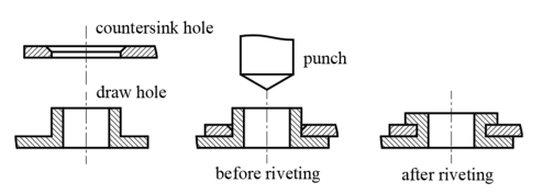
The inner drum is formed by crimping and riveting thinner plates, and the riveting method is flanging riveting. Flanging riveting is one of the main ways of connecting thin plates, and is mainly used to connect coated steel plates or stainless-steel plates. The forming mechanism (Figure 1) is that after the draw hole of one sheet metal part is matched with the countersink hole of the other sheet metal part, the peripheral wall of the draw hole is turned over and pressed against the other workpiece with a round punch to connect the two workpieces.
Figure 1. Forming mechanism of flanging riveting.
When the washing machine rotates at a high speed, the clothes will generate greater internal pressure on the inner drum due to centrifugal force. For the riveting area, the main force is shear, so it is necessary to consider the shear strength of the flanging riveting. There have been many studies on the shear strength of rivet connections. For self-punching riveting, the thickness of steel plate is the main factor affecting its shear performance (Xie et al. 2020). The shear strength of electromagnetic riveting is basically the same as that of pressure riveting, but its fatigue performance is about 1- 3 times that of pressure riveting (Li et al. 2017). The main failure mode of friction stir blind rivet (FSBR) under the action of shear force was the tension mode, that is, the fracture of material tissue fiber (Wang et al. 2017). Shear test was conducted on rivets to found that the shorter the riveting head, the greater the impact of bending on the joint (D'aniello et al. 2011). Researchers compared the shear tests of different rivets and found that solid self-piercing riveting (SSPR) had the highest strength (Mucha et al. 2015).
In this paper, ANSYS was used to establish the finite element model of the inner drum
Intelligent Human Systems Integration (IHSI 2022): Integrating People and Intelligent Systems https://openaccess.cms-conferences.org/#/publications/book/978-1-7923-8988-7 of a cylinder washing machine and carry on the statics analysis to get its stress distribution. The experimental test was carried out and the simulation results were compared to verify the simulation results.
ESTABLISHMENT OF FE MODEL Simplification of FE model
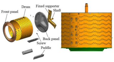
The inner drum of a cylinder washing machine is composed of 1 front panel, 1 drum, 1 back panel, 1 fixed supporter, 1 shaft, 6 screws and 3 paddles, as shown in Figure 2. Considering that the deformation of the fixed supporter is very small after the uniform pressure is applied in the drum, which is similar to a rigid body, the fixed supporter and shaft can be omitted, and the fixed constraint can be directly applied to the screws connected with the fixed support. For simulation and experimental comparison, paddles have also been omitted. In order to ensure the mesh quality and improve the calculation accuracy, we simplified the model. The basic ideas are as follows :(1) Bubbles and drainage holes on the surface of the drum were removed; (2) Fillets and chamfers which have little effect on the result were omitted; (3) Thin- walled structures such as the front panel, drum and back panel were simplified into shells.
Due to the complex structure of the riveting area, in order to improve the calculation accuracy and reduce the calculation time, the drum model was optimized. The solid model was adopted in the riveting area and the shell model was adopted in the other areas, as shown in Figure 2. The solid elements and shell elements were connected by RBE2.
Figure 2. Schematic(left) and optimization model (right) of the inner drum.
Meshing and materials Solid185 elements were applied to screws and the solid part of drum. Each node of the solid185 element has three translational degrees of freedom along the x, y and z directions. Shell181 elements were applied to the front panel, back panel and the shell part of drum. Each node has 6 degrees of freedom, three of which are translational
Intelligent Human Systems Integration (IHSI 2022): Integrating People and Intelligent Systems https://openaccess.cms-conferences.org/#/publications/book/978-1-7923-8988-7 along x, y and z directions and three are rotational around x, y and z axes respectively. Shell181 element supports most nonlinear constitutive models, including rate- independent plasticity, visco-plasticity/creep and hyperelasticity models. It has the functions of interface data definition, analysis and visualization. And it also can define composite multilayer shells. Material and mechanical properties of each component are shown in Table 1.
Table 1. Materials and mechanical properties of various components Component Material Young’s modulus / MPa Poisson’s ratio
Contact and boundary conditions The contact between the front panel and the drum, between the drum and the back panel, and between the screws and the drum are bonded contact. The contact at the riveting area of the drum is frictional.
Since the back panel is connected with the fixed supporter through screws, the connecting surface between the screws and the fixed supporter can be considered as the rigid surface, so the fixing constraint is directly set at these six screws.
As a result of centrifugal force, clothes will produce greater force on the inner wall of the drum. The maximum load of this washing machine is 17kg (including the mass of clothes and water) and the highest speed is 1420rpm. Assuming that the clothes are uniformly arranged in the drum, a annular uniform load with the thickness of 40mm is used to simulate the load. After calculation, the uniform pressure acting on the inner wall of the drum at the highest speed is 0.15569MPa.
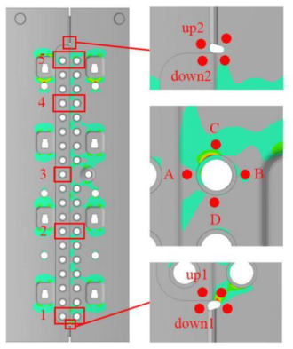
FINITE ELEMENT ANALYSIS Equivalent stress distribution in riveting area of the drum is shown in Figure 3. Taking the area around the gaps and nine rivets as the research objects, four positions A, B, C and D were taken around each rivet, and four positions were taken around the two gaps to obtain the simulated stress, as shown in Figure 3. Table 2 list the simulation results of test points around the rivets.
Intelligent Human Systems Integration (IHSI 2022): Integrating People and Intelligent Systems https://openaccess.cms-conferences.org/#/publications/book/978-1-7923-8988-7
Table 2. Simulation results of test points around rivets Positio n Stress around left rivets/MPa Stress around right rivets/MPa 1 2 3 4 5 1 2 4 5 A 80.7 31.8 39.9 29.2 136.1 51.05 37.48 49.84 66.71 B 22.1 20.0 58.5 34.3 33.21 45.21 52.30 38.61 89.11 C 26.0 16.5 45.9 22.3 56.05 132.9 87.88 116.7 154.8 D 38.1 22.1 45.4 29.5 45.89 132.3 114.9 111.0 70.38
Table available in the original PDF paper.
Figure 3. Equivalent stress distribution in riveting area and positions of test points Taking rivet 2 as an example, due to the centrally symmetric structure of the drum, the stress around the left rivets is less than that around the right rivets.
As for the rivets on the left side, rivet 2, 3, 4 were taken as examples. It is obvious that the stress around rivets 3 was greater than that around rivet 2 and 4. This is because rivet 3 is a single-row rivet, while rivet 2 and 4 are double-row rivets. Therefore, for the rivets on the left side, rivet 3 need to bear more stress.
As for the rivets on the right side, rivet 2 and 4 were taken as examples. It is obvious that the stress in positions C and D is greater than that in positions A and B. It shows that for the rivet on the right side, the stress in the vertical direction is greater than the stress in the horizontal direction.
Table 3. lists the stress results of test points around the gaps.It shows that there is stress concentration around the gaps due to structural mutation.
Table available in the original PDF paper.
Intelligent Human Systems Integration (IHSI 2022): Integrating People and Intelligent Systems https://openaccess.cms-conferences.org/#/publications/book/978-1-7923-8988-7
Table 3. Simulation results of test points around the gaps Stress around gaps/MPa up1 down1 up2 down2
Table available in the original PDF paper.
Left 24.55 43.05 41.02 15.92 Right 175.08 81.30 53.92 98.32
EXPERIMENTAL VERIFICATION Experimental equipment
The equipment used in the experiment includes wireless strain gauge, strain rosette, router, 3 washing machines and computer.
Experimental procedure Step 1: Open a rectangular groove on the plastic cylinder wall outside the drum, which is convenient to stick strain rosettes on the drum.
Step 2: Select the positions to stick strain rosettes. Before sticking, wipe the surface of drum with alcohol to remove oil and other stains, and then use 502 glue to paste the strain rosettes on the corresponding positions.
Step 3: Lay out the wires, and pay attention to protect the insulating paint outside the wires from being worn off, otherwise it will cause a short circuit.
Step 4: Place the load in the washing machine, and pay attention to distribute the load evenly on the wall of the drum as much as possible.
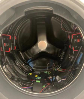
Step 5: Use cable ties to fix the wireless strain gauges on the wall of the drum and try to distribute them symmetrically to reduce the eccentric force during testing, thereby reducing vibration. Wiring, load arrangement and fixing of strain gauges are shown in Figure 4.
Step 6: Start the machine and let the washing machine work at a stable speed of 1420rpm for 3min to test the stress at different positions of the drum.
Intelligent Human Systems Integration (IHSI 2022): Integrating People and Intelligent Systems https://openaccess.cms-conferences.org/#/publications/book/978-1-7923-8988-7
Figure 4. Internal experiment layout of washing machine Experimental results
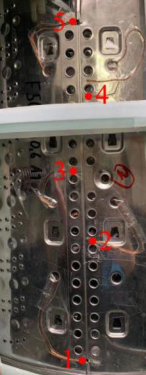
Stress test was conducted on the riveting area of the three washing machines, and the positions of the test points is shown in Figure 5. Point 1 and 5 are near the gaps, and point 2, 3 and 4 are around the rivets. In order to investigate the stress distribution of a single rivet at different positions, two test points are taken around the same rivet: point 2 and point 2’. Point 2 is located above the rivet and point 2' is located on the right side of the rivet. Table 4 shows the experimental test results of the test points.
(a) (b) (c)
Figure 5. Strain rosette positions of test points for the first machine (a), the second machine
Intelligent Human Systems Integration (IHSI 2022): Integrating People and Intelligent Systems https://openaccess.cms-conferences.org/#/publications/book/978-1-7923-8988-7
(b) and the third machine (c)
Table 4. Experimental results of riveting points Stress at riveting points /MPa
Average 76.73 141.10 90.08 22.90 133.51 161.19 Standard deviation 3.51 3.31 0.66 2.60 0.24 4.33
Compare the experimental results at point 2, 3 and 4 with the simulation results, it is obvious that for both experimental results and simulation results, the stress of the point 2 and point 4 is greater than that of point 3. This is because that point 3 is on the left side while point 2 and point 4 are on the right side. According to the previous conclusions, the stress of rivets on the left side is less than that of rivets on the right side, so the experiment verifies the simulation results well.
Compare the experimental results at point 2 and 2’ with the simulation results, it is obvious that for both experimental results and simulation results, the stress at point 2 is greater than that at point 2', that is, the stress in the vertical direction is greater than that in the horizontal direction. The experiment is consistent with the simulation.
Intelligent Human Systems Integration (IHSI 2022): Integrating People and Intelligent Systems https://openaccess.cms-conferences.org/#/publications/book/978-1-7923-8988-7
CONCLUSIONS
For this type of cylinder washing machine inner drum, its stress distribution in the riveting area is relatively uniform, all below the yield stress (280MPa). The centrally symmetric structure of the drum causes the stress to be large on right side and small on left side. For the rivets on the left side, rivet 3 has to bare more stress. For the rivets on the right side, the stress in the vertical direction is greater than that in the horizontal direction. Due to the structural mutation, the most vulnerable failure positions are near the gaps (maximum 175MPa) and around the rivets near the gaps (maximum 155MPa).
REFERENCES
Lim, H.T., Jeong, W.B. and Kim, K.J. (2010), “Dynamic Modeling and Analysis of Drum-type Washing Machine.” International Journal of Precision Engineering and Manufacturing, 11(3), 407-417. Nygards, T. and Berbyuk, V. (2012), “Multibody modeling and vibration dynamics
analysis of washing machines.” Multibody System Dynamics, 27(2), 197-238. Chen, H.W. and Zhang, Q.J. (2011), “Stability analyses of a vertical axis automatic washing machine with a hydraulic balancer.” Mechanism and Machine Theory, 46(7), 910-926. Xie, Z.Q., Zhang, A.L., Yan, W.M. et al. (2020), “The Shear Behavior and
Calculation Method of Self-piercing Riveted Connections on Thin-walled Steel Sheets.” Engineering Mechanics, 37(06), 234-245. (in Chinese) Li, G.Y., Jiang, H., Zhang, X. et al. (2017), “Mechanical properties and fatigue behavior of electromagnetic riveted lap joints influenced by shear loading.” Journal of Manufacturing Processes, 26, 226-239. Wang, W.M., Khan, H.A., Li, J. et al. (2017), “Classification of Failure Modes in
Friction Stir Blind Riveted Lap-Shear Joints With Dissimilar Materials.” Journal of Manufacturing Science and Engineering-Transactions of the Asme, 139(2). D'aniello, M., Portioli, F., Fiorino, L. et al. (2011), “Experimental investigation on shear behaviour of riveted connections in steel structures.” Engineering Structures, 33(2), 516-531. Mucha, J. and Witkowski, W. (2015), “Mechanical Behavior and Failure of Riveting
Joints in Tensile and Shear Tests.” Strength of Materials, 47(5), 755-769.
Intelligent Human Systems Integration (IHSI 2022): Integrating People and Intelligent Systems https://openaccess.cms-conferences.org/#/publications/book/978-1-7923-8988-7
LISTED IN THE AHFE DIGITAL BOOKSTORE CATALOGUE
Explore the complete digital volume
Intelligent Human Systems Integration (IHSI 2022): Integrating People and Intelligent Systems
Read this individual research paper free through the original publisher, or explore the full digital proceedings book.
ISBN 978-1-7923-8988-7
Explore this ISBN in the AHFE Bookstore ↗Listed in the July 2026 bookstore catalogue; search by ISBN to confirm current availability · Digital book purchase optional