Ziyao Zhao, Wang Haining, Baoqi Zhou (2022). Development of a finite element head model for contact pressure study of N95 Respirator. In: Ergonomics In Design. AHFE Open Access, vol. 47, pp. 98–104. https://doi.org/10.54941/ahfe1001925
The research on the comfort design of head-worn products using Chinese head and face anthropometric survey is of great importance for this country with the largest population in the world. In this study, a three-dimensional finite element head model was established by using the statistics of facial soft tissue thickness (FSTT) data obtained from the high-precision CT images of 1174 Chinese subjects. The headform was divided into multiple facial regions and composed by four layers including the skin, muscle, fat, and bone to achieve more realistic characterization of soft- and hard-tissue facial anthropometry in three dimensions. This paper presents a combined experimental and computational study on simulation of the contact pressure between an N95 filtering facepiece respirator (FFR) and the 3D Chinese reference headform. The finite element model (FEM) was validated by offline experiments using force sensing resistors (FSR) sensors. The FEM can be utilized for digital ergonomic assessments and help designers predict and evaluate comfort for more human-centered designs of head-mounted products.
Physical ergonomics is concerned with human anatomy, as well as anthro- pometric, physiological, and biomechanical characteristics, which are crucial for head-worn products, such as masks and goggles. Well-designed produ- cts that fits properly to the head and face can improve wearing comfort and avoid facial pressure injuries.
FEM has fundamentally revolutionized the way to do scientific modeling and engineering design, ranging from automobiles, aircraft, and wearable products since virtually every conceivable problem that can be described by partial differential equations. Many scholars and practitioners have used finite element analysis to study wearing comfort and fit of head-worn pro- ducts. The representativeness of headforms plays an important role in finite element analysis. 3D reference head models were utilized in several previous studies. (Lei et al., 2010) investigated the contact between respirators and five head models representing the facial composition of American workers. The headforms contain three layers: the skin, muscle, and bone, while the face was divided into four parts. (Lee et al., 2019) studied the faces of Korean Air
Development of a Finite Element Head Model for Contact Pressure Study 99
Force pilots (n = 336) and the heads of Americans (n = 2,299), analyzed the contact pressure of the pilot oxygen mask and virtual reality (VR) headsets. However, these headforms don’t have representative evidence as support on the soft tissue thickness of each layer. To the best of our knowledge, there has been no finite element head model built upon a large scale 3D Chinese head scans and CT images.
The aim of this study is to establish a FE head model based on a large number of Chinese head data for the comfort design of head worn devices. First, the establishment process of a finite element head model was proposed, then a multi-level and multi-region headform was established using the 50th percentile Chinese reference model built in (Wang et al., 2018), and a high- precision CT scan database with the sample size of 1174. Furthermore, a finite element contact pressure test between an N95 respirator and the FE headform was conducted and the computational results were validated.
SIMULATION MODEL AND METHOD The FE Models
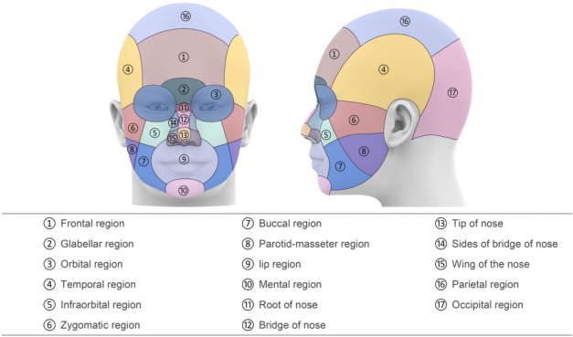
(Wang et al., 2018) developed five reference headforms with different shape and size using 33 facial measurements from 1900 3D head scans in Chi- nese Headbase survey, which was enriched to the size of 3400. In this study, a multi-level and multi-region headform was conducted based on the 50th percentile headform developed in (Wang et al, 2018). The thickness of each layer and region of the head was measured from a high-precision CT scan database consists of 1174 subjects. All CT image subjects were from the CT databases of the First Hospital of Changsha and the Third Xiangya Hospital of Central South University. The head was divided into 17 parts according to (Pansky & Gest, 2013; Paulsen & Waschke, 2013; Schuenke, 2016; Zarins, 2018), as shown in Figure 1. Each region contains four layers including skin, fat, muscle, and bone, from the surface to the inside. The thickness of each layer was measured through CT image processing. The tissue thi- ckness at a specific landmark was taken as the overall tissue thickness for that corresponding region.
The procedures are as follows: first, the STL file of the head model was imported into Geomagic Wrap 2017 (3D Systems, Rock Hill, SC, US) to tran- sfer triangular surfaces to Non-uniform rational B-splines (NURBS). After the noise was removed and the roughness was reduced, the surface fitting was performed to generate a STP file, which was imported into the Solidw- orks 2019 (Dassault systems, Paris) and divided according to the facial soft tissue thickness of different head regions, and then saved as an x-t file.
An Artec Spider 3D scanner (Artec Group, Luxembourg) was used to scan a 3M 1860 N95 respirator to obtain the point-cloud model, which was war- ped to a polygon model and refined to a symmetrical model. To represent different materials, the model was offset inward to form two separate layers where the thickness of the outer layer is 0.5mm thick and the inner layer is 2mm thick. Finally, the polygon model was transformed into a CAD model.
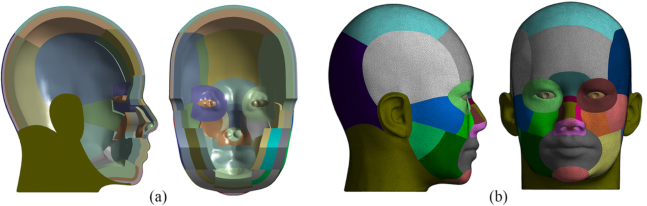
Figure 1: Regions of the head.Figure 2: FE models of the headform: (a) cross-sectional views, (b) left and front views.
Simulation Methods ANSYS Workbench 17 (ANSYS, Inc, PA, USA) was used to generate the FE meshing for both the headform and respirator models to which material pro- perties were assigned. FE models of the headform are shown in Figure 2. In this study, the material model of each level of the head model was assu- med to be the isotropic elastic material with uniform tensile properties in both directions. Mechanical properties of the headform and two layers of the mask used in this study were the same as properties used by (Lei et al., 2012), while the elastic material properties of the nose clip were adapted from (Cai et al., 2017). Mechanical properties of all FE models are listed in Table 1.
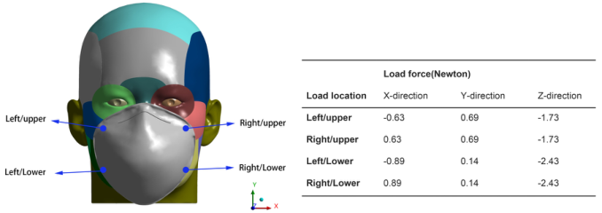
Figure 3 shows the strap loads applied on four locations including the left/upper, right/upper, left/lower and right/lower regions. It was assumed that the head would not move during the whole contact process. Six degrees of freedom of the node constraining the innermost surface of the bone layer were fixed, while the N95 FFR can move toward the headform with no constrained degrees of freedom.
In the initial stage, the N95 FFR and headform were assembled with a 3mm gap in between to prevent penetration, then the load force to the four
Development of a Finite Element Head Model for Contact Pressure Study 101
Table 1. Material properties of FE models.
Table available in the original PDF paper.
FE Models Components Young’s Modulus (Mpa) Poisson Ratio Density (g/cm3)
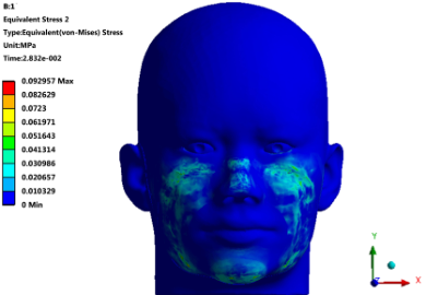
Figure 3: Locations and directions of loads.Figure 4: Pressure distributions on the FE head model.
corners of the mask was applied and the N95 FFR started moving toward the headform. When the respirator became stable on the headform, a force of 2N was applied on both sides of the nose clip along the negative direction of the z-axis, and the nose clip of the mask was adjusted to fit the nose. Finally, the N95 FFR was almost stable on the headform and the pressure distributions in the contact zones were finalized.
Figure 5: Five key areas on the head model.Table 2. Maximum of the contact pressures on five areas (Unit: Mpa).
Table available in the original PDF paper.
Area 1 Area 2 Area 3 Area 4 Area 5 pressure 4.37e-02 1.54e-02 6.60e-03 4.29e-02 1.31e-02
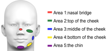
Simulation Results The contact pressure distribution on the head model is unequally distributed, as shown in Figure 4. The full circumference of the face was sealed over by the respirator. High contact pressures was found mainly in areas including the nasal bridge, top of the left cheek, top of the right cheek, middle of the left and right cheek, bottom of the left and right cheek, and the chin. In addition, the highest pressure occurred over the nasal bridge and needs to be further improved to achieve better comfort.
The contact pressures on five key areas (as shown in Figure 5) were obtained from the simulation results. The maximum value in the area were measured, as shown in Table 2. The nose (area 1) exhibits the highest pres- sure, followed by the pressure on the lower cheek (area 4), upper cheek (area 2) and chin (area 5), while the pressure on the middle cheek (area 3) is the smallest. According to the simulation results, air leakages happened adjacent to areas that have high pressures, namely, an uneven distribution of pressure on the contact area causes air leakages. Thus, areas adjacent to the high contact pressure areas could possibly have air leakage issues. That is, areas adjacent to nasal bridge, upper cheek, and lower cheek could have air leakages.
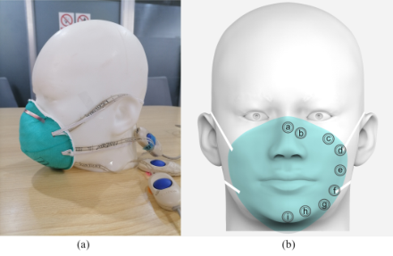
OFFLINE PRESSURE EXPERIMENT The contact pressure experiment was conducted using the FE head model and a 3M 1860 N95 mask. Force sensing resistor (FSR) film sensors (FlexiForce A201 1lbs, Tekscan Inc, USA; ±3% accuracy) were used in this experiment to measure the pressure forces between the headform and the mask. Nine areas on one side of the face were selected for contact pressure test since the head model is symmetrical. The locations of the areas are shown in Figure 6. The procedures are as follows: Firstly, the N95 respirator was put on the head- form to assure that respirator straps were in the correct position. Secondly, film sensors were inserted between the headform and the mask and pressure forces were recorded after the reading was stable for 3 consecutive seconds. All experiments were repeated three times.
Development of a Finite Element Head Model for Contact Pressure Study 103
Figure 6: (a) FSR film sensors between the mask and headform (b) Nine regions selected for pressure test.Table 3. Pressure forces on nine regions (Unit: N).
The results shown in Table 3 indicate that the stress concentration zones from the online FE analysis is in accordance with the offline pressure expe- riment. The pressure at region A is the highest, which corresponds to the maximum stress at the nose bridge in the FE analysis. Accordingly, region C and D correspond to the upper cheek, while region F and G correspond to the lower cheek, and region I corresponds to the chin. It was found that the pressure at region E is the smallest, which corresponds to the smallest stress in the middle cheek.
CONCLUSION
In this study, a multi-level and multi-region head model was developed by using statistics of soft tissue thickness from 1174 CT images of Chinese sub- jects. The model was divided into four layers, and the thickness of each layer was modeled according to the mean value of the tissue thickness on corre- sponding facial landmarks. The FE model has good representativeness and can be used for the finite element analysis of head-worn products. However, there are some limitations to be improved in the future. first, the ears haven’t been rebuilt according to the soft tissue thickness from the CT images, so can not perform the pressure simulation for ear worn products such as earpho- nes. Second, the model was divided into four layers including the skin, fat, muscle and bone, however, the model wasn’t designed continuously among layers and regions, which is not in accordance with the human head anatomy.
The virtual simulation of wearing an N95 mask was performed using the FE reference headform developed in this study. Five key areas were selected for stress and displacement measurement because of the noticeable high pres- sure within these five areas. Besides, an off-line experiment was conducted
and the contact pressure between the face and mask was measured. Nine regi- ons on the head were selected for pressure measurement. It was found that the stress concentration areas from the online simulation were in consistent with experiments which means the FE head models built in this study can be applied in the ergonomics design and evaluation of head worn devices.
REFERENCES
Cai, M., Shen, S., Li, H. (2017). The effect of facial expressions on respirators contact pressures. Comput Methods Biomech Biomed Engin, 20, 1122–1131. Lee, W., Kim, J. -G., Molenbroek, J. M., Goossens, R.H. and You, H. (2019). Estima-
tion of facial contact pressure based on finite element analysis. Appl Hum Factors Ergon Conf, Springer, 657–667. Lei, Z., Yang, J., Zhuang, Z. (2010). Contact Pressure Study of N95 Filtering Facepiece Respirators Using Finite Element Method. Comput Aided Des Appl, 7, 847–861. Lei, Z., Yang, J., Zhuang, Z. (2012). Headform and N95 Filtering Facepiece Respi-
rator Interaction: Contact Pressure Simulation and Validation. J Occup Environ Hyg, 9, 46–58. Pansky, B., Gest, T. R. (2013). Lippincott’s Concise Illustrated Anatomy: Head & Neck. Wolters Kluwer Health/Lippincott Williams & Wilkins. Paulsen, F., Waschke, J. (2013). Sobotta Atlas of Human Anatomy, Vol. 3, English:
Head, Neck and Neuroanatomy. Urban & Fischer Verlag/Elsevier GmbH. Schuenke, M., Schulte, E., Schumacher, U. (2016). Thieme Atlas of Anatomy, Volume 3: Head, Neck and Neuroanatomy, 2nd ed. New York, Stuttgart, Delhi, Rio de Janeiro: Thieme Medical Publishers. Wang, H., Chen, W., Li, Y., Yu, Y., Yang, W. and Ball, R. (2018). A 3D Head
Model Fitting Method Using Chinese Head Anthropometric Data. International Conference on Cross-Cultural Design, Springer, 203-215. Zarins, U. (2018). Anatomy of Facial Expressions. 3rd ed. Seattle, WA, USA: Exonicus, Inc.
LISTED IN THE AHFE DIGITAL BOOKSTORE CATALOGUE
Explore the complete digital volume
Ergonomics In Design
Read this individual research paper free through the original publisher, or explore the full digital proceedings book.
ISBN 978-1-958651-23-0
Explore this ISBN in the AHFE Bookstore ↗Listed in the July 2026 bookstore catalogue; search by ISBN to confirm current availability · Digital book purchase optional