Fadi Alnaimat, Bobby Mathew (2025). Simulation based study on heat transfer in microchannel heat sink with square ribs surface. In: Human Factors in Software and Systems Engineering. AHFE Open Access, vol. 181, pp. 56–63. https://doi.org/10.54941/ahfe1006394
A simulation-based study is carried out on microchannel heat sink with smooth surface and square ribs embedded surface. The heat sink is made of microchannels where each channel is 150 μm in width, and 1 cm in length. Water is used to study the heat sink. The study is conducted for a range of Reynolds numbers, from 100 to 500. The fluids' inlet and outlet temperatures, and the surface temperatures are used to calculate the thermal performance. According to the investigation, a higher Reynolds number raises the heat transfer coefficient and increasing Nusselt number. Additionally, it has been noted that raising the Reynolds number lowers the friction factor. It was evident that the square ribs microchannel had a higher heat transfer rate than the smooth channel. Additionally, it is observed that the heat sink with square ribs microchannels overall friction factor is higher than the heat sink with smooth channels. It is also found that the pressure drop increases with increasing Reynolds number.
Microchannels, which are commonly described as flow tunnels with a hydraulic diameter of less than 1000 µm, are being used more and more in heat transfer devices of all sizes (Mathew & Weiss, 2015). The advantages of microchannels include improved surface area density and enhanced heat transfer coefficient, which can lead to either an increase in the device’s heat duty for the same volume or a decrease in the device’s volume for the same heat duty (Mathew & Weiss, 2015). The quest for improving the heat transfer coefficient in microchannels continues to this day. There are several passive techniques for raising the heat transfer coefficient in microchannels. Changing or partially restricting flow pathways is a common practice in passive techniques.
Numerous variations of the microchannel, a passive technique for enhancing heat transmission, have been studied to better understand their performance (Mathew et al., 2010; Zheng et al., 2013a, 2013b). Only three walls—the bottom wall, two sidewalls, and the zigzag microchannel itself—are subject to a constant heat flux. Numerical research was done by
Simulation Based Study on Heat Transfer in Microchannel Heat Sink 57
Sui et al. (2010) to understand the performance of wavy microchannels in laminar flow.
They investigated three different situations: constant temperature, constant heat flux, and conjugate heat transfer. They compared the performance of each case to that of a straight microchannel under similar conditions. Mathew et al. (2010) used simulation-based research to examine the performance of two different zigzag microchannel designs under continuous heat flux. Heat flux is applied to every wall of the microchannel. They used the Nusselt number and friction factor to gauge performance. Zheng et al. (2013a) examined the thermohydraulic performance of a microchannel with a square cross-section and rounded corners when the heat flux was constant. The thermal performance of microchannels under conditions of continuous heat flux was determined. Some studies were carried out experimental testing on minichannel to examine heat transfer enhancement including (Daadoua et al., 2024 and Alnaimat et al., 2020). Microchannel can be utilized in different heat transfer applications (El Kadi et al., 2021; Alnaimat et al., 2023).
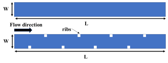
This work focuses on microchannels with square cross-sections and ribs on the sidewall, as seen in Figure 1. The heat flux is distributed on the microchannel’s two sidewalls. The performance of the microchannel is determined using the friction factor and Nusselt number. This study will analyse a microchannel’s performance in relation to its Reynolds number. The channel width W = 150 µm, and channel length L = 1 cm. Two different microchannels were examined including channel with smooth and square ribs with ribs dimension of 20 µm × 20 µm. The distance between each ribs is 1 mm. Despite some studies by Alnaimat et al. (2023) discusses the impact of the manifold on the flow maldistribution, this analysis assumes that the flow is uniform in all channels.
Figure 1: Schematic of microchannel view smooth and square ribs indicating dimensions and flow direction.
MATHMATICAL MODELING The microchannel depicted in Figure 1 is described using a mathematical model. It consists of the continuity equation, energy equation, and Navier- Stokes equations. Alnaimat et al. (2024) state that the continuity equation is represented by Equation (1), the Navier-Stokes equations by Equation (2), and the energy equation by Equation (3).
58 Alnaimat and Mathew
Equations and mathematical formulas are available in the original paper PDF.
ρfCp,fVf·∇Tf = kf∇2Tf (3) Where Vf (m/s) is the the fluid velocity vector, Pf (Pa) is the static pressure of the fluid, Tf (K) represents the static temperature of the fluid, µf (Pa.s) is the fluid viscosity, ρf (kg/m3) represent the fluid density, kf (W/mK) is the fluid thermal conductivity and Cp,f (J/kgK) is the fluid specific heat capacity. The flow is assumed to be Laminar in the microchannel, and negligible heat loss between the microchannel and the surrounding environment, and negligible viscous heat transfer.
This study’s modeling is established using a mathematical modeling approach similar to that described by Alnaimat et al. (2022, 2024). Boundary conditions for the model include the following: The microchannel’s inlet has a known velocity vector, as shown by Equation (4); its temperature at the inlet is known, i.e., Tf,in = 293 K; its four walls have no-slip flow conditions; its outlet has zero gauge pressure, or Pf,out = 0; Equation (5) shows that a constant heat flux is applied to the two sidewalls of the microchannel; and its top wall and outlet are adiabatic.
Vf,inRe
µf ρfDhy
m2 (5) where q′′ is the heat flux applied to the walls, and Dhy (m or µm) is the hydraulic diameter of the microchannel. The simulation is carried out using the Fluent module of Ansys Workbench. The SIMPLE algorithm is used in this paper. Once the field variables are determined, the Nusselt number and friction factor are obtained using equations (6) and (7), respectively.
2 L cos θ ρfu2
In microchannels, Nuavg represents the average Nusselt number, favg the average friction factor, havg (W/mK) the average heat transfer coefficient, 1Pf (Pa) the pressure drop between the inlet and outlet, and uf (m/s) the average velocity within the microchannel. The microchannel’s average heat transfer coefficient is obtained using equation (8).
Simulation Based Study on Heat Transfer in Microchannel Heat Sink 59
Equations and mathematical formulas are available in the original paper PDF.
′′ " h
# (8)
The LMTD is the log mean temperature difference represented by the fluid’s inlet temperature ¯Tf,in, the fluid’s average outlet temperature ¯Tf,out, the the temperature of the edges surface at the microchannel’s inlet ¯Tw,in and at its outlet ¯Tw,out.
The fluid used in the study is water and its thermophysical properties used are (ρf = 1000 kg/m3, µf = 0.001006 Pa.s, kf = = 0.597 W/mK and Cp,f = 4181 J/kgK). Studies are done for Reynolds number ranging from 100 to 400 and parametric study is carried out to understand the influence of hydraulic diameter, and Reynolds number.
Several assumptions underlie the model, such as minimal viscous dissipation and external heat transfer, steady state operation, functioning in a continuum regime, and no phase shift during flow. Since the validity of the continuous regime pertaining to flow in microchannels has already been established by researchers, this work employs computational fluid dynamics without any modifications.
RESULTS AND DISCUSSION
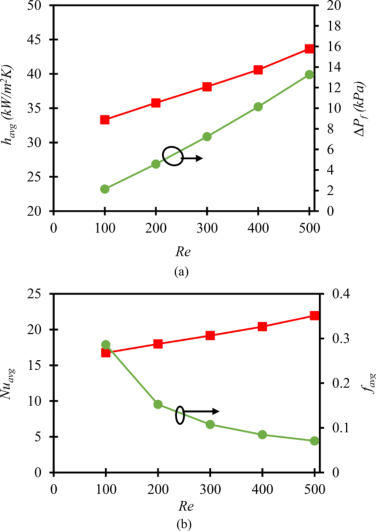
The heat transfer coefficient and pressure drop of square rib microchannels with Reynolds numbers ranging from 100 to 500 are displayed in Figure 2.a. The vertical axis on the right indicates the pressure drop, and the vertical axis on the left indicates the heat transfer coefficient. The relationship between the friction factor and Nusselt number and Reynolds number for square ribs microchannels across the same range of Reynolds numbers is shown in Figure 2.b. The vertical axes on the left and right, respectively, display the friction factor and Nusselt number. The friction factor and Nusselt number of the square ribs microchannel are higher than those of the straight microchannel because it is clear that the square ribs microchannel has a higher pressure drop and heat transfer coefficient than the smooth microchannel. The rise in the heat transfer coefficient at a given Reynolds number is caused by the frequent breakdown of boundary layers and the emergence of secondary flows, which are flows that are perpendicular to the main direction of flow.
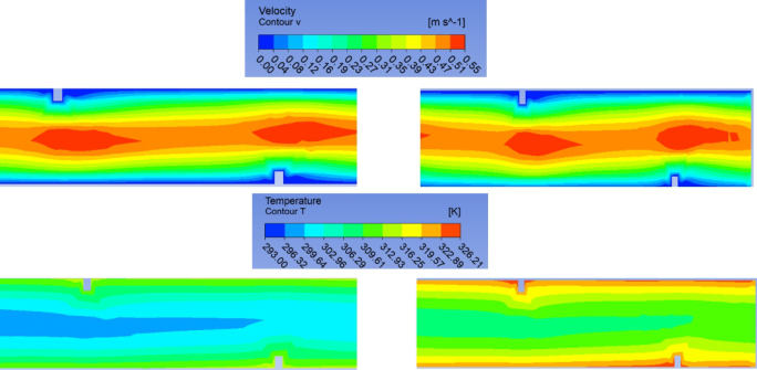
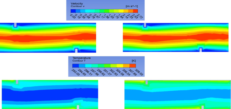
It is clear that square ribs microchannels break the boundary layers when the velocity contours of the smooth and square ribs microchannels are shown at similar locations along the microchannel’s length in Figure 3. It is clear that both the Nusselt number and the heat transfer coefficient increase as the Reynolds number grows. This is because secondary flows are intensifying and the boundary layer is more disturbed. At every Reynolds number considered in this work, the heat transfer coefficient and Nusselt number of a square ribs microchannel are higher than those of a smooth microchannel, and the discrepancy grows as the Reynolds number rises. The velocity and temperature contours at the designated locations of the
60 Alnaimat and Mathew
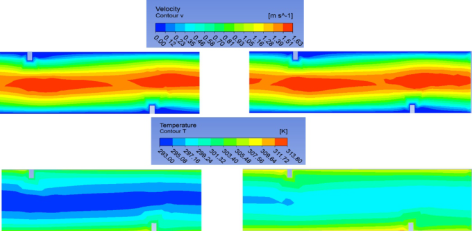
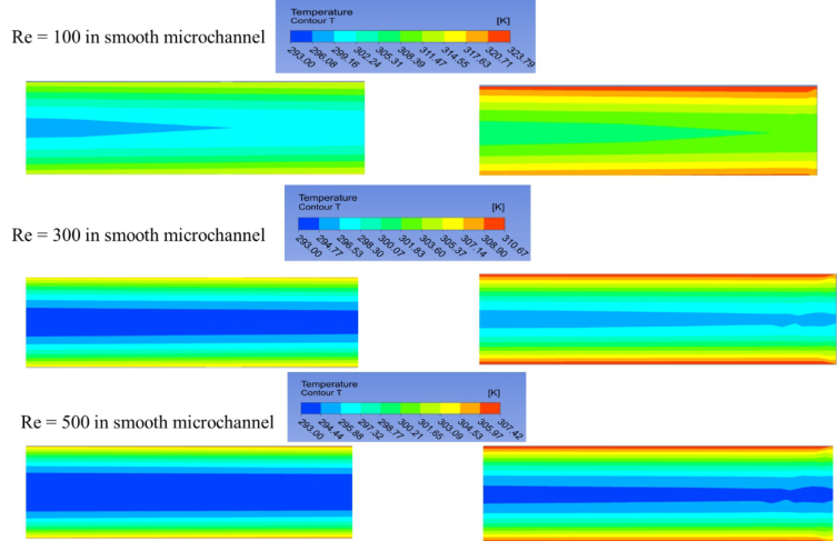
microchannels (middle and outlet) with square ribs surface are displayed in Figure 3, Figure 4 and Figure 5 at Re =100, 500 and 500, respectively. The temperature contours at the designated locations of the microchannel with smooth surface are displayed in Figure 6 for different Reynolds numbers Re = 100, 500 and 500. In both the smooth and square ribs microchannels, it is clear that the temperature is highest at the lowest Reynolds number. Additionally, it is demonstrated that the channel corners and the areas close to the two side surfaces exhibit the highest temperature.
Figure 2: Comparison of (a) havg and 1P with Re and (b) Nuavg and favg with Re of square ribs microchannels ( ) havg or Nuavg and ( ) 1P or favg (Dhy = 300 µm, L = 1 cm).
As illustrated in Figure 2.a, the pressure drop associated with square ribs microchannels is greater than that of smooth microchannels for a given Reynolds number because of the frequent disruption of boundary layers and the presence of secondary flows in square ribs microchannels as opposed to straight microchannels. As can be shown in Figure 2.b, the friction factor of the square ribs microchannel is larger than that of the smooth microchannel for the same Reynolds number. The friction factor of both smooth and square rib microchannels is observed to decrease as the Reynolds number increases, despite the fact that the pressure drop increases. The relationship between the Reynolds number and the Nusselt number is depicted in Figure 2.b, in contrast. As the Reynolds number increases, the friction factor falls due to the way it is computed. The friction factor is inversely proportional to the square of the average flow velocity and directly proportional to the pressure drop. However, the observed decrease in friction factor with Reynolds number can be explained by the fact that the pressure drop increase with Reynolds
Simulation Based Study on Heat Transfer in Microchannel Heat Sink 61
number is less than the square of the average flow velocity increase with Reynolds number, even though both the pressure drop and average flow velocity increase with increasing Reynolds number.
Figure 3: Velocity and temperature contour plot at location 1 and 2 of square ribs for Re = 100 (Dhy = 300 µm, L = 1 cm).Figure 4: Velocity and temperature contour plot at location 1 and 2 of square ribs for Re = 300 (Dhy = 300 µm, L = 1 cm).
62 Alnaimat and Mathew
Figure 5: Velocity and temperature contour plot at location 1 and 2 of square ribs for Re = 500 (Dhy = 300 µm, L = 1 cm).Figure 6: Temperature contour plot at location 1 and 2 of smooth channel for Re = 100, 300, 500 (Dhy = 300 µm, L = 1 cm).
CONCLUSION
In this study, the thermohydraulic performance of microchannels with square ribs under a constant heat flux was thoroughly investigated. The performance is examined using the friction factor, Nusselt number, heat transfer coefficient, and pressure drop across the 100–500 Reynolds number range. The friction factors, pressure drops, heat transfer coefficients, and Nusselt numbers of microchannels with square ribs are found to be greater
Simulation Based Study on Heat Transfer in Microchannel Heat Sink 63
than those of smooth microchannels. In this paper, the effect of Reynolds number on the performance of microchannel with smooth surface and square ribs is investigated. It has been determined that an increase in Re results in a higher enhanced heat transfer coefficient as well as a higher pressure drop.
ACKNOWLEDGMENT
The authors acknowledge funding from United Arab Emirates University through grant (#12R231 and #12R127).
REFERENCES
Alnaimat F., El Kadi K., Mathew B., CFD investigation of R134a and Propane condensation in square microchannel using VOF model: Parametric study using steady state solution, Journal of thermal science and engineering progress, 2023, 38, 2451–9049 Alnaimat, F., Mathew, B. (2023) “Flow distribution in microchannel devices with
U-shaped manifolds,” International Journal of Thermofluids, vol. 19, p. 100391. Alnaimat, F., Rahhal, A., Mathew, B. (2024) “Thermal and hydraulic performance investigation of microchannel heat sink with sidewall square pin-fins,” Results in Engineering, vol. 21, p. 101896. Alnaimat, F., Varghese, D., Mathew, B., (2022) “Investigation of thermal and hydraulic performance of MEMS heat sinks with zig-zag microchannels,” International Journal of Thermofluids, vol. 16, p. 100213, Nov. Alnaimat F., Ziauddin M., Experimental investigation of Heat Transfer in Pin-fins
heat sinks for cooling application, Journal of Heat and Mass Transfer, 2020, 1–7. Daadoua M., Mathew B., Alnaimat F., Experimental investigation of pressure drops and heat transfer in minichannel with smooth and pin fin surfaces, International journal of Thermofluids, 2024, 21, 100542. El Kadi K., Alnaimat F., Sherif S. A, Recent advances in condensation heat transfer in
mini and micro channels: A comprehensive review, Applied Thermal Engineering, 2021, 117412. Mathew, B. & Weiss, L. (2015), MEMS Heat Exchangers, in Materials and Failures in MEMS and NEMS, editors A. Tiwari and B. Raj, Scrivener – Wiley, 63–120. Mathew, B., John, T. J. & Hegab, H. (2010), Dynamics of Fluid Flow in a Heated
Zig-Zag Square Microchannel, 10th AIAA/ASME Joint Thermophysical and Heat Transfer Conference, 28 June – 1 July 2010, Chicago, IL, USA. Steinke, M. E. & Kandlikar, S. G. (2004), Review of Single-Phase Heat Transfer Enhancement Techniques for Application in Microchannels, Minichannels and Microdevices, International Journal of Heat and Technology, 22, 3–11. Sui, Y., Teo, C. J., Lee, P. S., Chew, Y. T., Shu, C. (2010), Fluid Flow and Heat Transfer
in Wavy Microchannels, Int. Journal of Heat and Mass Transfer, 53, 2760–2772. Zheng, Z., Fletcher, D. F. & Haynes, B. S. (2013), Chaotic Advection in Steady Laminar Heat Transfer Simulations: Periodic Zigzag Channels with Square Cross-Sections, International Journal of Heat and Mass Transfer, 57, 274–284. Zheng, Z., Fletcher, D. F. & Haynes, B. S. (2013), Laminar Heat Transfer Simulations
for Periodic Zigzag Semicircular Channels: Chaotic Advection and Geometric Effects, International Journal of Heat and Mass Transfer, 62, 391–401.
LISTED IN THE AHFE DIGITAL BOOKSTORE CATALOGUE
Explore the complete digital volume
Human Factors in Software and Systems Engineering
Read this individual research paper free through the original publisher, or explore the full digital proceedings book.
ISBN 978-1-964867-57-1
Explore this ISBN in the AHFE Bookstore ↗Listed in the July 2026 bookstore catalogue; search by ISBN to confirm current availability · Digital book purchase optional