Johannes Klotz, Sascha Hasenoehrl, Sven Matthiesen, Marcus Geimer (2026). Design of a Hydraulic Substitute Base for Demolition Hammers. In: Human Interaction and Emerging Technologies (IHIET-FS 2026): Future Systems and Design Applications. AHFE Open Access, vol. 235, pp. 334–344. https://doi.org/10.54941/ahfe1007287
Substitute bases for demolition hammers should emulate mineral materials. Their advantage over mineral materials is that they are not destroyed by the energy of high-frequency impacts, enabling repeatable tests for the development of demolition hammers. To date, no substitute bases are known that can represent a wide range of different materials in an equivalently effective manner. This paper presents a hydraulic substitute base whose stiffness and damping can be adjusted by varying oil volume, orifice cross-section, and preload pressure.
Demolition hammers are machines used to crush mineral materials and building materials. Central to their performance is the impact mechanism, which transfers energy into the chisel and the base. The resulting impact forces shatter the material in the vicinity of the chisel tip. For the further development and evaluation of such machines, physical testing remains indispensable, since simulations with simplifying modeling assumptions cannot fully eliminate residual uncertainties. Tests on mineral material bases are only partially suitable: the base is destroyed during testing, which complicates long-duration tests. In addition, demolition hammers are predominantly used on natural or nature-based building materials whose inherent inhomogeneity reduces reproducibility. Especially for the tests required by the EU directive (European Parliament and Council, 2006) to assess vibration emissions, high repeatability is essential. Therefore, “artificial” test bases, called substitute bases, are used to reproduce the behavior of mineral materials in an equivalently effective way with low scatter. Existing solutions, such as the steel ball energy absorber Dynaload specified in DIN EN ISO 28927-10, are predominantly mechanical and only partially fulfill the requirements defined in (Klotz et al., 2026a). In particular, the Dynaload system, which is designed for noise, vibration and performance testing of rotary hammers, is not intended as an adjustable base that can represent different mineral materials via adjustable parameters (PNEUROP Tools Committee, 2005). Klotz et al. (2026a) propose the development of a hydraulic substitute base Received April 10, 2026; Revised April 26, 2026; Accepted May 15, 2026; Available online June 22, 2026
Design of a Hydraulic Substitute Base for Demolition Hammers 335 as an equivalently effective, repeatable, adjustable, and low-wear alternative. Owing to the low compressibility of hydraulic fluids, high impact forces can be handled; at the same time, hydraulic components enable a defined setting of stiffness and damping (Klotz et al., 2026a).
CONTRIBUTION In this study, a novel hydraulic substitute base for demolition hammer testing is presented, enabling a physically interpretable and adjustable emulation of material behavior. The key contributions are summarized as follows:
1. A hydraulic-based substitute concept is developed to achieve equivalently effective, repeatable, and low-wear testing conditions for demolition hammers. The impact behavior can be adjusted using three key hydraulic parameters: o the oil volume (hydraulic capacity), determining the effective stiffness o the orifice cross-section (hydraulic resistance), controlling the damping characteristics o the preload pressure, defining the maximum feed force
2. A mechanical design implementation is realized, enabling precise and repeatable adjustment of stiffness and damping.
The proposed system is validated through simulation and experimental results, demonstrating its capability to emulate impact behavior under high dynamic loads.
STATE OF THE ART AND RESEARCH Mechanical Substitute Base
Substitute bases are used for the experimental testing of demolition hammers to reproducibly emulate the characteristics of mineral materials. In practice, mechanical systems predominate; a prominent example is the steel-ball energy absorber Dynaload referenced in DIN EN ISO 28927- 10 for hand-held percussive tools (DIN, 2011). It enables standardized comparative measurements; however, it is not intended as an adjustable base for reproducing different minerals and building materials (PNEUROP Tools Committee, 2005). For damping hydraulic-hammer impacts, a substitute base built up in layers from different materials has been described (Park et al., 2005). According to the authors, the substitute base, which cannot be adjusted to alter its damping properties, can compact over time, thereby unintentionally changing its properties. Thus, an equivalent, adjustable, repeatable, and low-wear emulation of real bases remains an open challenge.
Hydraulic Substitute Base In addition to mechanical substitute bases, Klotz et al. (2026a) evaluated pneumatic and mechatronic concepts regarding their suitability: Purely mechanical spring-damper systems are only limitedly variable and can be prone to wear. Pneumatics are unsuitable for representing hard bases due to
their high compressibility. Electromechanical concepts tend to fail because of the required short strokes combined with high impact forces. In contrast, hydraulic systems, due to the low compressibility of liquids, allow high impact forces to be combined with small penetration depths and enable the targeted adjustment of stiffness and damping via oil volume and orifice cross- section. A systematic comparison therefore identifies hydraulics as the most promising approach for an equivalently effective, adjustable, repeatable, and low-wear substitute base. (Klotz et al., 2026a) Klotz et al. (2026a) discuss potential arrangements for hydraulic substitute bases and select the concept “tool as cylinder piston” due to its ability to injects energy directly into the cylinder, thereby avoiding reflections from additional contact partners.
For this concept, Klotz et al. (2025) have shown via simulation that, by varying hydraulic parameters, the hydraulically dissipated energy can be set between 0% and 84% of the initial impact energy. Their contribution describes a co-simulation as a design tool: a structural-mechanical FEM impact model of the impactor components of a rotary hammer according to Hasenoehrl et al. (2025) is coupled bidirectionally with a hydraulic base model (capacity, resistance, optionally inductance) via an FMI-based coupling. Tool displacements are fed into the hydraulic model. The resulting hydraulic pressure or reaction force is returned to the FEM model and applied to the tool. The dynamic interaction between impact mechanism and base can thus be captured more realistically than with rotary-hammer models according to Golycheva et al. (2003) and Riederer (1985), since those only limitedly represent the influence of impact-body geometry on the propagation of impact-induced strain waves. (Klotz et al., 2025) Using the co-simulation described in Klotz et al. (2025), Klotz et al. (2026a) carried out a virtual configuration of a hydraulic substitute base for a rotary hammer with 4.2 J impact energy (Bosch GBH 4-32). Parameter variations show that, with suitable hydraulic capacity and hydraulic resistance, both penetration depth and dissipated energy can be specifically adjusted; for a typical concrete penetration depth of ~0.4 mm and maximum damping of 84%, a mineral oil volume of 0.3 ml and an orifice cross-sectional area of about 1.1 mm² is required at a preload pressure of 15 bar. A larger volume and smaller orifice cross-section is required for lower damping at the same penetration depth (Klotz et al., 2026a).
DESIGN Requirements
Klotz et al. (2026a) define requirements for a substitute base for rotary hammers. Design requirements can be derived from these and further considerations:
Realistic tool geometry with SDS-plus groove
Adjustability of hydraulic capacity o High stiffness (low hydraulic capacity) for reproducing hard minerals o Range of the oil volume: 0.3−5 ml
Adjustability of hydraulic resistance o Repeatable setting of the resistance
Design of a Hydraulic Substitute Base for Demolition Hammers 337 o Temperature-independent operating behavior o Orifice cross-sections:
Adjustability of pressure preload:
Pressure resistance up to 500 bar
Low friction and leakage in the tool guidance
High wear resistance
Mounting option for sensors, including pressure sensors, strain gauges, an optical displacement measurement system, and a temperature sensor.
Technical Implementation
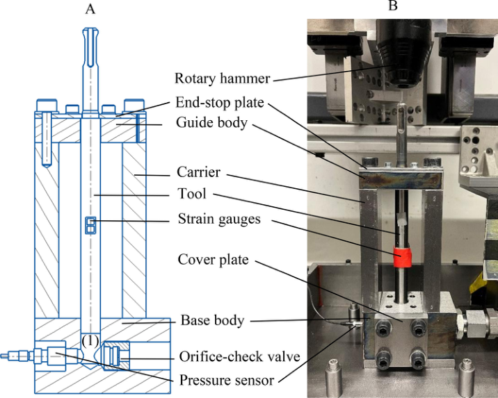
Figure 1 shows the hydraulic substitute base for a rotary hammer and its cross- sectional drawing. The tool is radially guided at the bottom (base body) and in the upper section (guide body). At the top, it features an SDS-plus interface via which it can be clamped into a rotary hammer. Strain gauges are bonded to the middle of the tool to prove effect equivalence and to validate the setup. The tool rests on an oil column (1). The oil pressure can be measured via the screwed-in pressure sensor. Opposite the pressure sensor, orifice-check valves with different cross-sections can be screwed in. The damping can be influenced via the orifice cross-section. The integrated check valve enables the tool to quickly return to its initial position. The oil volume can be varied by inserting cover plates with different plunger lengths, thereby changing the hydraulic capacity. A hydraulic hose connects the substitute base to the valve block, with which the system can be preloaded. This chapter describes the rationale behind the mechanical design. The technical drawings are published in (Klotz et al., 2026b).
Figure 1: Hydraulic substitute base for rotary hammers: (A) sectional drawing, (B) photo.
Tool The tool was manufactured from a rotary-hammer chisel listed in (Klotz et al., 2026b). Care was taken to keep geometric changes to the rotary- hammer chisel as small as possible. At the rotary hammer end of the large- diameter section, a shoulder was turned to provide a defined, stroke-limiting end-stop. The chisel tip was removed, first because a center bore was needed for the grinding process, and second because making small oil volumes is easier with a cut tip. The large-diameter section was ground down from 13.9 mm to 13.292 mm. This grinding process was necessary to obtain a high- quality cylindrical form. This enables low-leakage and simultaneously low- friction guidance of the tool in the base body. In addition, distortion from the hardening process, which increases wear resistance, had to be corrected. During the hardening process, a hardness of 60 HRC (Rockwell C) was achieved. This was done to ensure high wear resistance. To avoid destroying the hardness of the lateral surface through heat input during cutting, the center bore can be removed by wire EDM. An alternative process would be waterjet cutting.
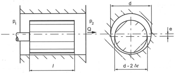
Tool Guidance and End-Stop The tool is radially guided at the bottom via the bore in the base body. To increase wear resistance, the base body was hardened. This resulted in a hardness of 60 HRC (Rockwell C). To prevent the tool from jamming in the base body, it is additionally radially guided at the top in a guide bore. To ensure the collinearity of the guide bores and enable the tool to move up and down with minimal friction, grinding of the bores was carried out in a single setup. For this purpose, the carrier and the guide body were bolted to the base body clamped in the cylindrical grinder using dowel-pin connections. The upper bore was ground first. The guide body was then removed and the guide bore in the base body, which was still clamped to the machine, was ground. An end-stop plate can be screwed onto the guide body to limit the upward stroke of the tool. The fit between the tool and the base body also serves as a gap seal, eliminating the need for elastic, friction-inducing elastomer seals. The volume flow QL,exzent. across an eccentric sealing gap, as in Figure 2, can be calculated as follows, where e describes the eccentricity, d describes the cylinder’s diameter, Δr describes the difference in radii, l describes the length of the slot, η describes the dynamic viscosity, and p1 – p2 describes the pressure difference across the gap (Murrenhoff, 2016):
2 3
(1) L,exzent. 1 2 1 1.5 ( ). 12 η
e d r Q p p r l
Equations and mathematical formulas are available in the original paper PDF.
Figure 2: Volume flow through an eccentric sealing gap (Murrenhoff, 2016).
The bore exhibits a total cylindricity of 3 μm, and the tool a total cylindricity of 1 μm. The difference in radii between base body and tool bore is Δr = 2.3 μm. At a pressure differential of Δp = 15 bar, with the dynamic viscosity η40°C = 40. 10−3 N ∙ s/m2, the diameter, d = 13.297 mm and the length l = 8.6 mm, the leakage according to Equation (1) at maximum eccentricity is 0.03 ml/min. However, the leakage value depends heavily on the difficult- to-measure delta r. During operation, the leakage prove to be negligible. Based on the sensation felt by hand, the frictional force also appears to be negligible. The clearance between tool and guide body was deliberately made larger, since oil tightness is not required: Δr = 10 μm.
Adjustability of Oil Volume To realize adjustability of the oil volume, cover plates with different plunger lengths can be bolted to the side of the base body. This allows the oil volume to be varied between 2.8 ml and 5.3 ml. The bodies are sealed by a soft- annealed copper washer, which exhibits higher stiffness than an O-ring. The size of the washer was chosen to be as small as possible so that no air remains when the oil is filled. An externally adjustable mechanism via a piston–thread arrangement would require additional seals and would be more elastic.
Adjustability of Orifice Cross-Section The damping behavior can be influenced via the orifice cross-section. Adjustability is realized via screw-in valves with different orifice sizes. In this way, the orifice cross-sections can be set precisely and repeatably, which would be difficult with a continuously adjustable orifice. The orifice geometry in the screw-in valves is known and easy to model. The valves include an integrated check valve that enables the tool to be quickly pushed back to its initial position. The used valves, including orifice diameters between 0 mm and 2 mm are listed in (Klotz et al., 2026b). They exhibit high stiffness due to their small oil volume.
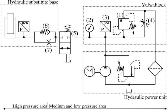
Pressure-Preload System A hydraulic power unit listed together with other components in (Klotz et al., 2026b) is used to preload the system pressure. Connected to the power unit is a valve block that includes a preload valve (1), a pressure gauge (2), a
pressure sensor (3), and an adjustable throttle valve (4) as shown in Figure 3. The pressure preload can be set at the preload valve.
Figure 3: Hydraulic circuit diagram of the substitute base system.
The preload can be read on the pressure gauge; the pressure sensor (2) also records it. The throttle valve (4) is not necessary if the flow rate from the power unit is low enough to be regulated by the pressure relief valve. If only a power unit with a higher delivery flow is available, the required pressure preload can be regulated by the adjustable throttle. The valve block is connected to the substitute base via a hose line and a ball valve (5), which is used for the venting process. The check valve (6) enables the cylinder to be fed at a high flow rate past the resistance (7) while the tool is moving upwards. During the downward motion, the check valve closes and enables pressure build-up in the stiff section of the substitute base.
Cooling System Without cooling, the damping energy absorbed by the test rig would lead to a temperature rise. As a result, friction in the fit could change due to metal expansion. The temperature of the hydraulic fluid would also change, and thus its viscosity. Therefore, a cooling system is required to maintain constant behavior over long periods. In hydraulic systems, the hydraulic fluid is typically routed through an active oil cooler or passively cooled via residence time in the tank. In the substitute base, however, a sufficiently large quantity of fluid cannot be returned to the tank, because otherwise the damping would be too high and hard impacts could no longer be represented. The leakage flow through the sealing gap is so small that the newly supplied hydraulic oil is insufficient to maintain a constant oil temperature. The metal body surrounding the oil is therefore cooled. For this purpose, a CPU heat sink is mounted on the back of the metal body. It is traversed by water, which is subsequently cooled.
Design of a Hydraulic Substitute Base for Demolition Hammers 341 Sensors
The substitute base is equipped with sensors to capture penetration characteristics including damping. A piezoelectric pressure sensor listed in (Klotz et al., 2026b) is screwed into the base body; it allows recording of rapidly rising and falling pressure profiles. A vibrometer, a displacement measurement system listed in (Klotz et al., 2026b), records the tool’s displacement over time. Strain gauges listed in (Klotz et al., 2026b) bonded to the tool enable the recording of strain waves. Temperature sensors monitor the temperature of the base body and coolant.
Ensuring Pressure Resistance Pressures up to are to be expected in the high-pressure area as a result of the impact force. The test rig should therefore have sufficiently high-pressure resistance. In Figure 3, the rig is divided into high- and mid- to low-pressure areas. The housing walls in the high-pressure region are made of massive steel to minimize elastic deformation during pressure changes, thereby maintaining a high equivalent bulk modulus (i.e. low hydraulic capacity). The copper washer sits in a groove so that, in the event of rupture, the ring is not flung radially outward. The screw-in valves listed in (Klotz et al., 2026b) are specified up to a pressure of . In the event of failure, there is no danger to the surroundings, since the screw-in valve is surrounded by the massive base body, and a tube fitting is screwed into the same thread. The hydraulic capacity of the substitute base is small due to the small oil volume and the low compressibility of the pressure fluid, which also keeps the hazard potential low.
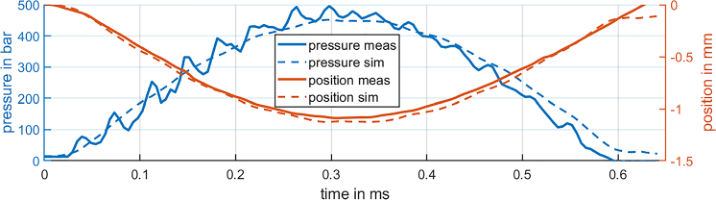
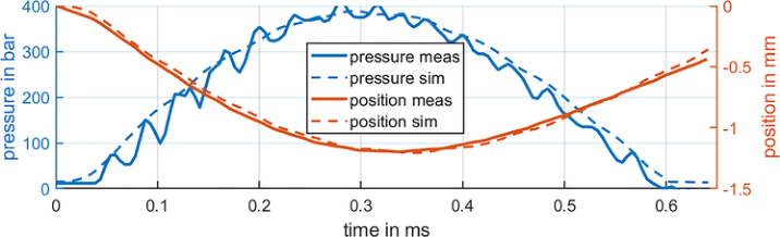
MEASUREMENT Figures 4 and 5 show a comparison of the simulation results and the measured values for two specific parameter combinations during a main stroke. Good agreement can be seen. Due to tool movement, pressure initially rises and then drops rapidly. Hydraulic damping, calculated according to (Klotz et al., 2025), accounts for 9% of the initial kinetic energy for the parameter set in Figure 4. Regarding the parameter set in Figure 5, the simulations yield a value of 45%, whereas the measured data results in only 42%.
Figure 4: Comparison of simulation results (sim) with measurements (meas) for an oil volume of 5.3 ml, an orifice diameter of 0.4 mm, and a precharge pressure of 15 bar. A Bosch GBH 4-32 with 4.2 J impact energy was used with an applied feed force of 150 N.Figure 5: Comparison of simulation results (sim) with measurements (meas) for an oil volume of 5.3 ml, an orifice diameter of 1.0 mm, and a precharge pressure of 15 bar. A Bosch GBH 4-32 with 4.2 J impact energy was used with an applied feed force of 150 N.
DISCUSSION
To test rotary hammers with repeatable accuracy, a hand-arm model should be used. These systems allow a defined contact force to be applied to the rotary hammer in the direction of the tool. If this feed force is greater than the preload pressure ppre multiplied by the tool cross-sectional area A, the rotary hammer, including the hand-arm model, moves toward the substitute base until the tool strikes the bottom of the bore. To avoid this, the preload pressure should be set so that the product ppre. A is greater than the contact force. A safety margin of approximately 10% is recommended. However, to prevent the rotary hammer, including the hand-arm model, from moving upwards until the tool has been pushed out of the base body, a stop is required. Such an external tool stop is not present on rotary hammers with chisels. There, a stop located in the rotary hammer limits the upward stroke of the firing pin and tool. It must therefore be assumed that the vibration emission can be influenced by the external stop. However, the energy damped during the main impact can be specifically adjusted.
The volume can be adjusted upwards to a sufficient extent. If necessary, the volume could be further increased by replacing the cover plate with a volume expansion chamber. Downwards, however, the adjustment option is limited. However, the primary tuning target is the damping energy, which can be fully adjusted even at greater penetration depths. Further measures to reduce the volume include the use of shorter carriers, the use of a milling cutter when producing the tool borehole or the use of a smaller restrictor check valves size. Currently, valves of size BC 30, listed in (Klotz et al., 2026b), with M20x1.5 thread and a pressure resistance of up to 500 bar are installed. A smaller size, for example BC 26, would also allow pressures of up to 700 bar (HAWE Hydraulik SE, 2024).
With the base body shown here, the tool may become stuck if the preload pressure is not set high enough, because the tool bore has not been fully ground to the bottom. This can be prevented by cutting a groove in the lower part of the bore. If the tool penetrates too deeply, it would then strike the bottom of the bore but would no longer jam.
Design of a Hydraulic Substitute Base for Demolition Hammers 343 When preparing for a test, it is important to ensure thorough venting to prevent trapped air from compromising stiffness. To do this, the tool must be disassembled and the oil must be drained until no air bubbles are visible.
CONCLUSION
This study proposes a novel hydraulic substitute base enabling adjustable and repeatable emulation of material behavior. This design allows the use of a tool with a geometry similar to that of a real chisel, while also achieving high stiffness and variable damping of impacts. The seal between the tool and the base body exhibits high rigidity with negligible friction and leakage. The walls of the high-pressure area, including the seals, are rigid, so that elastic deformation at high pressures does not significantly impair the rigidity of the base. The additional upper tool guide provides increased wear resistance, while at the same time providing sufficient space for sensors. The hydraulic resistance can be adjusted with repeatable accuracy via the screw-in orifices. The flow behavior is temperature-independent in turbulent flow. The valves used cover the required adjustment range, which can be fine-tuned as needed by machining the valves using wire EDM. The hydraulic capacity can be varied via the oil volume. Overall, the presented design solutions meet the defined design requirements.
OUTLOOK Further tests are being conducted to verify the variable damping behavior. Long-term tests are being carried out to prove wear resistance. In addition, the simulated strain is compared with the strain gauge measurement. The damping properties of mineral materials are analyzed using strain gauges and emulated using the hydraulic substitute base. An additional component is manufactured, which is screwed onto the base body and directs the oil into the reservoir during the venting process. This facilitates ease of handling. The procedure for developing the substitute base as well as the design solutions can be applied to substitute bases for larger demolition hammers, such as jackhammers, and hydraulic breakers.
ACKNOWLEDGEMENT
The project underlying this publication was funded by the Deutsche Forschungsgemeinschaft (DFG, German Research Foundation) under project ID 517363628. Responsibility for the content of this publication lies with the authors. We are grateful for the support.
AUTHOR CONTRIBUTION Johannes Klotz was responsible for conceptualization, original draft preparation, visualization, validation, formal analysis, and project administration. Johannes Klotz and Sascha Hasenoehrl were responsible for data curation, investigation, and software, with Johannes Klotz responsible for
simulation and Sascha Hasenoehrl responsible for measurements. Johannes Klotz and Marcus Geimer were responsible for the methodology, review and editing. Resources, supervision, and funding acquisition were provided by Marcus Geimer and Sven Matthiesen.
REFERENCES
Deutsches Institut für Normung (DIN). (2011). Handheld motor-driven machines – Methods for measuring vibration emission – Part 10: Rotary hammers, demolition hammers and breakers (DIN EN ISO 28927-10:2011-07; German version EN ISO 28927-10:2011). European Parliament and Council (2006): Directive 2006/42/EC of the European
Parliament and of the Council of 17 May 2006 on machinery, and amending Directive 95/16/EC (recast). Official Journal of the European Union, L157. Available at: http://data.europa.eu/eli/dir/2006/42/oj Golycheva, E.V., Babitsky, V.I. and Veprik, A.M. (2003). Dynamic correction of excitation in hand-held electro-pneumatic percussion machines. Journal of Sound and Vibration, 259(4), pp. 829–843. Available at: https://doi.org/10.1006/ jsvi.2002.5124 Hasenoehrl, S., Klotz, J., Geimer, M. and Matthiesen, S. (2025). NAFEMS simulation
and validation of contact forces in impact systems for developing an adjustable substitute workpiece. NAFEMS World Congress 2025, Salzburg, Austria. Available at: https://www.nafems.org/publications/resource_center/nwc25-0007167-paper/ HAWE Hydraulik SE (2024) Orifice plate check valve type BC. Available at: https:// productfinder.hawe.com/downloads/D6969_B-de.pdf. Accessed: 7 April 2026. Klotz, J., Hasenoehrl, S., Matthiesen, S. and Geimer, M. (2025). Co-simulation
of a hydraulic substitute substrate for the equivalent representation of mineral materials. DS 140: Proceedings of the 36th Symposium Design for X (DFX2025), pp. 1–10. Available at: https://doi.org/10.35199/dfx2025.03 Klotz, J., Hasenoehrl, S., Matthiesen, S. and Geimer, M. (2026a) Hydraulic substitute base for demolition hammers. In: Proceedings of the 15th International Fluid Power Conference (IFK), to be published. Klotz, J., Hasenoehrl, S., Matthiesen, S. and Geimer, M. (2026b) Design Drawings of
a Hydraulic Substitute Base for Rotary Hammers. Karlsruhe: Karlsruhe Institute of Technology. Available at: https://doi.org/10.5445/IR/1000192092 Murrenhoff, H. (2016). Lecture notes for Fundamentals of Fluid Mechanics / Hubertus Murrenhoff. Part 1: Hydraulics. 8th corrected edition. Aachen: Shaker Verlag. Park, J.-W. and Kim, H.-E. (2005). Development of the test system for measuring
the impact energy of a hydraulic breaker. Proceedings of the JFPS International Symposium on Fluid Power, 2005(6), pp. 75–79. Available at: https://doi. org/10.5739/isfp.2005.75 PNEUROP Tools Committee. (2005). Dynaload: Design, construction, use and maintenance – Power tools. Available at: https://doczz.net/doc/4598702/dynaload- --design--construction--use-and-maintenance Riederer, H. (1985). Investigations into the dynamics of electropneumatic drilling
hammers. Dortmund: Universität Dortmund.
LISTED IN THE AHFE DIGITAL BOOKSTORE CATALOGUE
Explore the complete digital volume
Human Interaction and Emerging Technologies (IHIET-FS 2026): Future Systems and Design Applications
Read this individual research paper free through the original publisher, or explore the full digital proceedings book.
ISBN 979-8-950676-11-6
Explore this ISBN in the AHFE Bookstore ↗Listed in the July 2026 bookstore catalogue; search by ISBN to confirm current availability · Digital book purchase optional