Paul Rosero, Felix Vidal, Roi Mendez, Martín Martínez (2026). Iterative Vision-Based Model to Measure the Contact-Tip-Working-Distance for WAAM Interlayer Control. In: Human Interaction and Emerging Technologies (IHIET-AI 2026): Artificial Intelligence and Future Applications. AHFE Open Access, vol. 201, pp. 347–357. https://doi.org/10.54941/ahfe1007189
Dimensional accuracy in Wire Arc Additive Manufacturing is frequently compromised by stochastic geometric variations, primarily layer height undulations and humping, which cause uncontrollable fluctuations between the build-up component and the welding wire, commonly referred to as Contact Tip-to-Work Distance (CTWD). This missdistance leads to arc instability and insufficient melt pool shielding, degrading final component quality. Therefore, this paper aims to develop an iterative vision-based model to detect and measure the CTWD losses by monitoring the model decay that triggers a continuous learning loop with a High-Performance Computing system, enabling the model to be retrained and updated to adapt to environmental changes, such as reflections, spatter, or new robot trajectories. This model has been quantized to run on an industrial PC for low-latency inference, while challenging frames from the welding camera are forwarded to an edge device for operator data annotation. This vision-based approach significantly improves control system efficacy by providing a proactive, measurable feedback signal for inter-layer adjustment decisions (repeat, skip, or proceed), thereby maintaining layer geometry and ensuring the long-term reliability of the WAAM process in dynamic manufacturing environments. As a result, a single-shot detector is selected as the object detection model, which weighs 8MB and runs at 60 frames per second.
Wire Arc Additive Manufacturing (WAAM) is a process that uses an energy source to weld metal wire layer by layer, building up a component according to the robot’s path planning (Zahidin et al., 2023). To ensure dimensional accuracy, the control system slices the workpiece into predefined layers and incorporates cooling periods between successive layers, thereby regulating heat accumulation. Therefore, the WAAM process is highly utilized in large metal components due to its fast deposition rate and relatively low manufacturing and equipment costs (Franke et al., 2025).
Within this context, the Cold Metal Transfer (CMT) configuration represents a modified Metal Inert Gas (MIG) welding process ed on short- circuiting transfer (Teixeira et al., 2021). Through the oscillation of the Received October 29, 2025; Revised January 14, 2026; Accepted January 19, 2026; Available online April 1, 2026
wire, CMT achieves a lower heat input compared to conventional welding technologies, which helps to reduce residual stresses. Nevertheless, the final shape and quality of the weld beads are strongly affected by the dynamic fluid behavior of the melt pool (Zahidin et al., 2023). These fluid dynamics are closely linked to several key process parameters, including welding current and voltage, welding speed, and wire feed rate. Moreover, variations in heat dissipation across the workpiece can lead to morphological changes in the deposited beads, resulting in differences in layer height at different positions, exhibiting a humping flaw (Babu et al., 2025). This layer height variations due to humping-induced undulations in the previous layer causes fluctuations in the distance between the welding nozzle and the top of the previous layer. Consequently, the contact tip-to-work distance (CTWD), varies stochastically during humping along the direction of deposition (Hauser et al., 2020). An increase in CTWD within valley regions restricts the flow of shielding gas, thereby compromising the protection of the melt pool. Insufficient shielding gas flow can also arise from nozzle clogging caused by spatter or excessive CTWD (Ramalho et al., 2025). As a result, this non-uniform bead geometry may cause structural weaknesses, residual stresses, and layer height variability (Baldauf et al., 2024). In this scenario, sensors and cameras can play a fundamental role to add extra information to the control system to track overheating, voltage or current fluctuations, and, most importantly, variations in CTWD (Feng et al., 2020; Oueslati et al., 2025) . Welding cameras can exclude the shielding gas region from their field of view and focus on the torch tip, enabling real-time measurement of CTWD. To perform this task, the robot’s routine is divided into small, layered subprograms that act in response to CTWD decisions. Building on this idea, this paper proposes the development of an inter-layer closed-loop imaged based control system designed to detect and accurately measure CTWD during the WAAM process. The system compensates for height loss caused by heat accumulation in the build-up component. Moreover, it is designed to be flexible enough to update the underlying model as working conditions change—for example, when robot trajectories, materials, torch reflections, or background components are modified.
As main results, a Single-Shot-Detection (SSD) model has been chosen to run in real, Yolov9 infers the bounding boxes in the Edge devices with a GUI that the operator can use to validate the process. The SSD model weighs 8MB and runs at 60 frames per second.
RELATED WORK
The WAAM process has been widely studied in several works, leveraging the base for physical and mechanical descriptions to apply on top of process AI models, providing a better understanding of concerns to tackle from various approaches. One of these concerns is the build-up height compensation, mostly using sophisticated sensing and control methodologies. This section provides a review of the literature with the evolution from traditional geometric control to advanced, AI-data driven systems for monitoring weld bead features or the CTWD.
Iterative Vision-Based Model to Measure the Contact-Tip-Working 349 Early efforts in WAAM control primarily addressed geometric errors using closed-loop or layer-by-layer compensation strategies. Thermal control is crucial to managing heat accumulation and its consequential effects on dimensional accuracy (Zahidin et al., 2023). Those works have shown the relevance of using a cooling system between layers or adequate cooling time to deposit a new layer. Conversely, (Li et al., 2021) pointed out methods to measure the layer geometry and update the robot’s deposition parameters for the subsequent layer based on sensors’ feedback. For its part, AI models, mainly Convolutional Neural Networks (CNNs), have demonstrated effectiveness in classifying and diagnosing process anomalies (So et al., 2024). For instance, various CNN architectures have been investigated and successfully classified defects such as humping and spattering with high accuracy (Ramalho et al., 2025; Xia et al., 2022). More relevant to the proposed work is the application of AI and vision systems to measure specific geometric features such as the CTWD, which is essential for arc stability and shielding gas efficacy (Novelino et al., 2022). Object Detection models, such as Mask R-CNN, have been successfully employed for image object detection and segmentation to accurately measure the melt pool width in WAAM. Building on this, the feasibility of camera-based measurement and control of the CTWD itself was recently validated (Baldauf et al., 2024; Franke et al., 2025). The direct control of CTWD compensates for variations in the height of the previously deposited layer (layer height control) (Xiong et al., 2021). This new approach opens the door to improve control systems with real-time image-based information. However, even though these works have shown the effectiveness of the CTWD detection in the height control system, they are mainly focused on a test bench setup with low variations in the environment.
METHODOLOGY
This section shows the proposed steps to accomplish the closed-loop control system with the iterative CTWD detection running in real-time. Therefore, it starts with the system setup to show all the WAAM cell components. Then, the AI pipeline starting from the data collection, annotation, models, optimizations, and model training. Finally, we show the target build-up components where the control system has been tested.
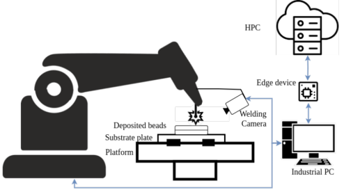
System Setup The WAAM working cell comprises an ABB robot, a Fronius TP400i as a power source with a CMT configuration, the Cavitar Camera C400 as the welding camera to detect the torch and the wire tip, Jetson AGX Orin is the selected edge device, and the HPC with several Nodes with GPUs to train models (Rani et al., 2024). The ABB robot gathers data from the power source by Profinet protocol and publishes it with its data from a TCP socket to the Industrial PC, which is the orchestrator of this data with the frames from the Welding camera. The camera works at 60Hz with the resolution of 1440*1080 px and 22 cm from the process. The Industrial PC and the
Edge device are in the same local network, sending data by HTTP calls. The Edge device can send JSON packages to the HPC system, which can send back JSON packages to the Edge and the Industrial PC as well. Fig. 1 shows graphically the system setup with its connections.
Figure 1: Monitoring system at WAAM working cell.
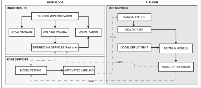
AI Pipeline The AI pipeline starts with the monitoring phase on the shop floor, where the Industrial PC gathers data from the welding camera. Some experimental trials of the WAAM process were conducted to get images from different positions and deposited beads to feed the dataset and annotate the data afterwards. Then, three object detection models were benchmarked to get adequate one to run in real-time. The selected model was chosen based on weight, accuracy, and execution time metrics, and then packed in ONNX format. Then, the model was quantized into 8 bits for GPU and/or optimization purposes. In this setup, we prioritize execution time over accuracy, as the model can be fine-tuned across trials. Therefore, a robust model is placed on the Edge device to annotate the images that the lighter model could not make good inferences. When the component has been finished, the operator can validate the new annotated data from the robust model, re-annotate if needed, and send it to the HPC to re-train models. The HPC is listening to the communication channel and when it detects new messages, stores the new images and trains the models, packages, and sends them to their corresponding site to run again with their updates.
The AI floor is in charge of running the developed algorithms to get the data and tailor it into the adequate formats that each model needs, train the model, store it in different folders, packages, and quantize the model to send it to the shop floor. Fig. 2 shows the shop floor and the AI floor components.
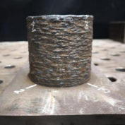
Build-Up Components Three different build-up components were defined to test the CTWD detection. With their robot’s routines, we could test all the possible directions that the camera has to follow to the robot, such as: Walls, Cylinder, and cantilevered T-shaped walls.
Figure 2: AI pipeline in the WAAM process.
RESULTS
This section highlights the results of the annotated data, the object detection models, their optimizations, and the interactions along several tests to avoid the model decay. Finally, with the optimized model running in real-time, the deposited bead compensation is described.
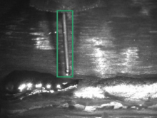
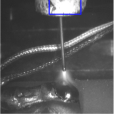
Annotated Data After several experimental trials, images were taken and manually annotated. The bounding box starts from the bottom of the torch until the wire tip. The setup was configured with 30, 60, and 90 seconds of cooling time between layers, where 500 images were annotated in three different stages: A) where the wire is going down; B) the wire touches the substrate or the previously deposited bead, creating the arc, and C) when the welding arc shows and the wire goes up, keeping the process stable. Fig. 3 shows each stage with their annotation box.
Stage A Stage B Stage C
Figure 3: Data annotated in different WAAM stages and the final bounding box.
Object Detection Models Based on the literature review, three object detection models have been evaluated for this research. YOLO models have been tested in several industrial scenarios with adequate performance. However, YOLOV9 is the
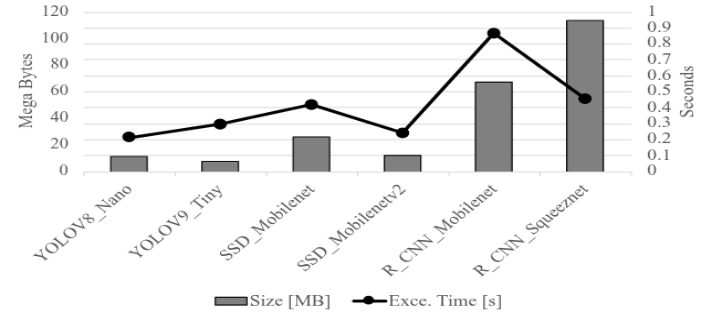
maximum version to be applied since the Python environment restrictions, which is installed in the monitoring system. Therefore, YOLOV8 and YOLOV9 were taken in place. For its part, SSD models, with the Mobilenet architecture as a feature extractor, have been proven of being a suitable object detector to run it in real-time systems. Conversely, R-CNN architectures are robust models that could detect objects in challenging environments. Therefore, all models were trained with their corresponding CTWD-dataset formats. All models were run in the HPC environment, where their execution time and model weights were measured. Fig. 4 shows that SDD models and R-CCN models used lighter CNN architectures, such as MobileNet and Squeeznet, since they could reduce the model complexity and size. In this scenario, after models were trained and packed in a ONNX format, R-CNN models show being a very robust detector, but they weigh over 70 MB, and on average, to infer a single image takes more than 0.4 seconds, which is far from the expected range (i.e., 60 HZ). For its part, YOLOV8 and V9 weigh under 10 MB, and they perform under 0.3 seconds per image. On the other hand, SSD models got similar results to YOLO models since they weigh 9 MB with the execution time per image of 0.3 seconds. Subsequently, all models were evaluated using the IoU and mAP metrics to assess the accuracy of the predicted bounding boxes and the feasibility of CTWD recognition throughout the test set. R-CNN and YOLO models perform similarly with high results, even though the test images are from different experimental trials with light reflections. Conversely, SSD models have good IoU and mAP metrics, but they sometimes fail with images that contain torch reflections. As a result, since we prioritize the execution time over the model performance on the industrial PC, SSD, and YOLO models were quantized and tailored to run in a GPU setup. On the other hand, YOLO models were deployed and tested in the Edge device for annotated images, with no detection from the real-time model.
Figure 4: Model performance comparison.
Iterative Vision-Based Model to Measure the Contact-Tip-Working 353 Iterations
Once the SSD Model was selected and integrated into the monitoring system, several walls of 33 beads were made to ensure the model’s performance. On each test, some conditions were slightly changed, such as:
The first wall has a black background, and the model can detect the CTWD, but in the next walls, the previous component had reflections to the camera’s laser and injected noise into the frames taken.
In some walls, clamps have shown in front of the camera with similar characteristics from the build-up component and it was detected as wrong CTWD.
The torch was covered with the anti-projection spray, but in previous tests, it was not; therefore, it made the torch shiny, and the model detects it as CTWD.
Although an anti-spatter spray is applied to the WAAM torch, metallic spatter still builds up after a few tests.
In some tests, to get a temperature representation, the monitoring system added thermocouples on the substrate. Therefore, their wires blind the camera, and the model incorrectly detects the wire as part of the torch, resulting in a false positive for the CTWD.
Those frames with new conditions that the model was not aware of, they feed the dataset. In some cases, the robust model, running out of the monitoring system, had to be updated as well. Fig. 5 shows an example of the thermocouples and how, after several iterations, the model was able to detect the CTWD correctly.
(a)Wrong Detection (b) Right detection (c) wire and CTWD
Figure 5: Model predicting the CTWD in real-time.
When the dataset finally shows all the possible data bias in the shopfloor, the SSD model performed accurately in detecting the CTWD. However, after testing the real component height, the average value that the model provided was 20\% under the real value. This error was more evident in the last welded beads. When we carefully check all the datasets, the CTWD was detected correctly, but we also recorded CTWD values when the welding arc is present, which is a wrong value since the power source is configured when
the CTWD touches the previous bead or the substrate. Therefore, a new annotation stage was made to get the bounding box of the arc, and if the model detects it, the CTWD is not measured. Fig. 5(c) when it detects both, the welding arc and the CTWD. With this new model, the CTDW values are fewer than the previous tests since we remove the CTWD value from images with arc, therefore, the build-up component height gotten from the object detection model is very similar to the 3D scan values that the piece was made.
Deposited Bead Compensation Once the Object detection model was optimized and it is running in the right compiler to make inferences in real-time, the CTDW value can represent the build-up component height and compares with the expected value from the robot’s trajectory. In this case, in the power source, the CTWD configuration was set in 16 millimetres, therefore, the robot takes this value and goes up each layer in its z-axis. With this, the build-up component does not lose height, and this control approach can do the times needed. On the other hand, if the CTWD is over the 16 mm, the robot can jump two layers to compensate that the component grew up more than the expected. Some tests were made to ensure the proposed control strategy, first, the Cantilevered T-shape was made with no CTWD control approach and a short cooling time between beads. As a result, in Fig. 6(a) shows the overheat at the last welded beads where dimensions were wrong and it did not reach the expected height. Conversely Fig. 6(b) was made with an adequate cooling time, but based on the temperature accumulation, it lost 10 layers that the control system acted and repeat those to reach the expected height.
(a) Under the height set (b) Right conditions (c) humping-induced porosity (d) Right conditions
Figure 6: Build-up components made and tested with the proposed system.
When the cylinder wall with the right cooling time between layers. Fig. 6(c) shows when the control approach is off, and since the heat accumulation due to the build-up dimensions, it lost 8 layers. Conversely, Fig. 6(d) the control system was compensating the component height and reached the expected dimensions.
CONCLUSION AND FUTURE WORKS This paper successfully proposes and outlines an Inter-layer Closed-Loop Control system for Wire Arc Additive Manufacturing (WAAM) centred on
Iterative Vision-Based Model to Measure the Contact-Tip-Working 355 the real-time measurement of the Contact Tip-to-Work Distance (CTWD). By leveraging a quantized Object Detection model running on an industrial PC, the system proactively detects CTWD fluctuations—a direct consequence of bead geometry errors and humping—and uses this information to trigger inter-layer decisions (repeat, skip, or proceed). This approach moves beyond traditional reactive control strategies that only compensate for layer height errors in deposition.
Crucially, the primary novelty of this work lies in the distributed AI floor architecture that ensures system longevity and adaptability. By establishing a continuous feedback loop involving an industrial PC for primary inference, an edge device for data validation, and an HPC system for targeted retraining, the model is resilient against the environmental noise inherent in real manufacturing settings, such as torch spatter, light reflections, and changes in robot programming.
Future work will focus on the empirical validation of this decentralized architecture, specifically quantifying the latency and precision gains from model quantization on the industrial PC, and demonstrating the effectiveness of the HPC retraining loop in mitigating model drift when exposed to significant changes in working conditions. This research paves the way for truly intelligent, self-adapting, and high-precision WAAM systems.
ACKNOWLEDGMENT
This project has received funding from the European Union’s Horizon Europe Research and Innovation program under Grant Agreement No. 101091449 PIONEER.
REFERENCES
Babu, A., Trodini, E., Argumedo, J. L. G., Richardson, I. M., & Hermans, M. J. M.
(2025). Correlating geometry, microstructure and properties of High Strength Steel thin wall structures fabricated with WAAM. Journal of Advanced Joining Processes, 11, 100292. https://doi.org/https://doi.org/10.1016/j.jajp.2025.100292 Baldauf, M., Lohrer, P., Hauser, T., Jauer, L., & Schleifenbaum, J. H. (2024). Camerabased measurement and control of the contact tip to work distance in wire arc additive manufacturing. Progress in Additive Manufacturing, 9(3), 565–574. https://doi.org/10.1007/s40964-024-00655-4 Feng, Y., Chen, Z., Wang, D., Chen, J., & Feng, Z. (2020). DeepWelding: A Deep
Learning Enhanced Approach to GTAW Using Multisource Sensing Images. IEEE Transactions on Industrial Informatics, 16(1), 465–474. https://doi.org/10.1109/ TII.2019.2937563 Franke, J., Heinrich, F., & Reisch, R. T. (2025). Vision based process monitoring in wire arc additive manufacturing (WAAM). Journal of Intelligent Manufacturing, 36(3), 1711–1721. https://doi.org/10.1007/s10845-023-02287-x Hauser, T., Silva, A. Da, Reisch, R. T., Volpp, J., Kamps, T., & Kaplan, A. F. H. (2020).
Fluctuation effects in Wire Arc Additive Manufacturing of aluminium analysed by high-speed imaging. Journal of Manufacturing Processes, 56, 1088–1098. https://doi.org/https://doi.org/10.1016/j.jmapro.2020.05.030
Jorge, V. L., Teixeira, F. R., Scotti, A., Scotti, F. M., & Siewert, E. (2023). The significance of supplementary shielding in WAAM of aluminium thin walls. Journal of Manufacturing Processes, 106, 520–536. https://doi.org/https://doi. org/10.1016/j.jmapro.2023.09.063 Kozamernik, N., Bračun, D., & Klobčar, D. (n.d.). WAAM system with interpass
temperature control and forced cooling for near-net-shape printing of small metal components. 110(7), 1955–1968. https://doi.org/10.1007/s00170-020-05958-8 Li, Y., Li, X., Zhang, G., Horváth, I., & Han, Q. (2021). Interlayer closed-loop control of forming geometries for wire and arc additive manufacturing based on fuzzy-logic inference. Journal of Manufacturing Processes, 63, 35–47. https://doi. org/https://doi.org/10.1016/j.jmapro.2020.04.009 Mu, H., Polden, J., Li, Y., He, F., Xia, C., & Pan, Z. (n.d.). Layer-by-layer model-based
adaptive control for wire arc additive manufacturing of thin-wall structures. 33(4), 1165–1180. https://doi.org/10.1007/s10845-022-01920-5 Novelino, A. L. B., Carvalho, G. C., & Ziberov, M. (2022). Influence of WAAM- CMT deposition parameters on wall geometry. Advances in Industrial and Manufacturing Engineering, 5. https://doi.org/10.1016/j.aime.2022.100105 Oueslati, S., Paquet, E., Belkadi, F., Ritou, M., & Le Bot, P. (2025). New monitoring
criteria for instability detection by Machine Learning in Additive Manufacturing: Application to Wire Arc Additive Manufacturing process. IFAC-PapersOnLine, 59(10), 2250–2255. https://doi.org/https://doi.org/10.1016/j.ifacol.2025.09.378 Ramalho, A., Assad, A., Bevans, B., Deschamps, F., Santos, T. G., Oliveira, J. P., & Rao, P. (2025). Understanding and detection of process instabilities in wire arc directed energy deposition additive manufacturing using meltpool imaging and machine learning. Materials & Design, 258, 114598. https://doi.org/https://doi. org/10.1016/j.matdes.2025.114598 Rani, F., Chollet, N., Vogt, L., & Urbas, L. (2024). Industrial Edge MLOps: Overview
and Challenges. In F. Manenti & G. V Reklaitis (Eds.), 34th European Symposium on Computer Aided Process Engineering / 15th International Symposium on Process Systems Engineering (Vol. 53, pp. 3019–3024). Elsevier. https://doi.org/ https://doi.org/10.1016/B978-0-443-28824-1.50504-4 Shah, A., Aliyev, R., Zeidler, H., & Krinke, S. (2023). A Review of the Recent Developments and Challenges in Wire Arc Additive Manufacturing (WAAM) Process. Journal of Manufacturing and Materials Processing, 7(3). https://doi. org/10.3390/jmmp7030097 So, M. S., Mahdi, M. M., Kim, D. B., & Shin, J.-H. (2024). Prediction of Metal
Additively Manufactured Bead Geometry Using Deep Neural Network. Sensors, 24(19). https://doi.org/10.3390/s24196250 Teixeira, F. R., Scotti, F. M., Reis, R. P., & Scotti, A. (2021). Effect of the CMT advanced process combined with an active cooling technique on macro and microstructural aspects of aluminum WAAM. Rapid Prototyping Journal, 27(6), 1206–1219. https://doi.org/https://doi.org/10.1108/RPJ-11-2020-0285 Xia, C., Pan, Z., Li, Y., Chen, J., & Li, H. (2022). Vision-based melt pool monitoring for
wire-arc additive manufacturing using deep learning method. The International Journal of Advanced Manufacturing Technology, 120(1), 551–562. https://doi. org/10.1007/s00170-022-08811-2
Iterative Vision-Based Model to Measure the Contact-Tip-Working 357 Xia, C., Pan, Z., Polden, J., Li, H., Xu, Y., Chen, S., & Zhang, Y. (n.d.). A review
on wire arc additive manufacturing: Monitoring, control and a framework of automated system. 57, 31–45. https://doi.org/10.1016/j.jmsy.2020.08.008 Xiong, J., Zhang, Y., & Pi, Y. (2021). Control of deposition height in WAAM using visual inspection of previous and current layers. Journal of Intelligent Manufacturing, 32(8), 2209–2217. https://doi.org/10.1007/s10845-020-01634-6 Yang, L., Sohn, H., Ma, Z., Jeon, I., Liu, P., & Cheng, J. C. P. (n.d.). Real-time
layer height estimation during multi-layer directed energy deposition using domain adaptive neural networks. 148, 103882. https://doi.org/10.1016/j. compind.2023.103882 Zahidin, M. R., Yusof, F., Abdul Rashid, S. H., Mansor, S., Raja, S., Jamaludin, M. F., Manurung, Y. H. P., Adenan, M. S., & Syahriah Hussein, N. I. (2023). Research challenges, quality control and monitoring strategy for Wire Arc Additive Manufacturing. Journal of Materials Research and Technology, 24, 2769–2794. https://doi.org/https://doi.org/10.1016/j.jmrt.2023.03.200
LISTED IN THE AHFE DIGITAL BOOKSTORE CATALOGUE
Explore the complete digital volume
Human Interaction and Emerging Technologies (IHIET-AI 2026): Artificial Intelligence and Future Applications
Read this individual research paper free through the original publisher, or explore the full digital proceedings book.
ISBN 978-1-964867-77-9
Explore this ISBN in the AHFE Bookstore ↗Listed in the July 2026 bookstore catalogue; search by ISBN to confirm current availability · Digital book purchase optional