Zhongqi Liu, Qian Yang, Qianxiang Zhou (2025). Biomechanics Simulation and Damage Analysis of Head and Neck on Extraction Aircrew Escape System. In: Accessibility, Assistive Technology and Digital Environments. AHFE Open Access, vol. 162, pp. 190–200. https://doi.org/10.54941/ahfe1006026
Currently, aviation lifesaving methods are mostly divided into ejection escape and traction rescue. Compared with ejection lifesaving, traction lifesaving technology is an active lifesaving method, and its advantages are simple structure, light weight, small space occupation, good stability, more suitable for low-speed light aircraft lifesaving. It uses the rocket to pull the crew out of the aircraft in an accident. The rocket first exits the cockpit, and then pulls out a rope to pull the crew out of the aircraft, and after a delay of a certain time, the parachute automatically opens, so that the crew can safely land on the ground. In order to avoid serious injury in the process of traction, it is necessary to study the stress of human head and neck joints which are most vulnerable to injury in the process of traction. In this study, CT image scans of the head and neck were performed on 2 volunteers who fit the body standards of pilots. MIMICS software was used to process the scanned image data and reconstruct the prototype of the human head and neck model. The model was further processed by geomagic software to obtain a complete and smooth head and neck geometric model. A complete head and neck finite element model was obtained by dividing the grid of the geometric model, setting the element format and material parameters of the body structure. The finite element model of head and neck was verified by axial impact test of cadaver from 0° and 15°. The results showed that the finite element model established in this paper has high accuracy. After processing the test data, the initial loading conditions of the traction rescue simulation were obtained, and the stress of the head and neck joints during the helicopter rescue was simulated. The LS-PrePost module in ANSYS software was used to obtain the data needed for dynamic response and damage analysis. Based on the HIC and NIC criteria, the head and neck injury during the life-saving process was determined. The results showed that the neck of the human body may be damaged during the positive traction, and the analysis of the obtained stress curve showed that the vertebrae may fracture at the maximum stress, and the intervertebral disc may be caused by overextension. In order to reduce the deformation of the cervical vertebra during the life-saving process of traction, a set of effective restraint system should be designed to restrain the human body and reduce the relative movement between various vertebrae in the neck, so as to better protect the cervical vertebra.
Aviation lifesaving is mainly categorized into two types: ejection lifesaving and traction lifesaving. Among them, traction lifesaving technology is an active lifesaving method. Compared with ejection lifesaving, its advantages are simple structure, lightweight, small space occupation, good stability, and more suitable for the lifesaving of low-speed light aircraft. Traction lifesaving uses rockets to pull pilots out of an aircraft that has been involved in an accident. The rocket is shot out of the cockpit and then a rope is pulled to pull the pilots out of the aircraft. After a certain delay, a parachute opens automatically, allowing the pilots to land safely on the ground.
The instantaneous position change or relative displacement that occurs during traction lifesaving, coupled with high G-value loads, may cause cervical muscle strains, cervical spine fractures, ligament tears, and intervertebral disc herniation. Therefore, the overload on the human body
Biomechanics Simulation and Damage Analysis of Head and Neck 191
need to be evaluated in the design, experimentation, and qualification of traction lifesaving systems to ensure the safety of the pilots during the lifesaving. In the study of human impact response, it is difficult to subject the human body directly to high-velocity and high-load experiments. To obtain experimental data on the human body’s response to high-speed loads, establishing computer simulation models has become one of the directions of injury biomechanics research. Because of the complex anatomical structure of the head and neck, the study of the biomechanical response and injury mechanism of the head and neck in traction rescue has been recognized as a difficult problem.
The current models used for head and neck biomechanical response simulation are mainly multi-rigid-body, concentrated mass, and finite element models. Lu utilized the established rigid-body model of the head and neck to analyze the dynamic response of the pilot’s head and neck during the arrested landing process, and discussed the effects of helmets on head-neck overload and muscle strain (Lu et al., 2012). Dai established two kinds of head finite element models with and without cervical vertebrae and analyzed the influence of the cervical vertebrae on the head’s mechanical response under the effect of the automobile collision impact loading (Dai et al., 2013). Wan constructed a finite element model of head and neck based on automobile collision tests to study its biomechanical response and damage mechanism under instantaneous impact (Wan et al., 2005). Li employed nonlinear viscoelastic materials to simulate brain tissue within the head- neck finite element model, achieving precise computational modelling and experimental fitting of brain tissue biomechanical responses (Li et al., 2010). Jiang performed high-speed impact response analysis on a human head- neck finite element model, acquiring dynamic response parameters of various tissues and determining injury status (Jiang et al., 2012).
This study established a human head-neck finite element model based on Chinese pilot anthropometric standards, conducted simulation analyses of biomechanical responses and injury mechanisms in the head and neck during ejection scenarios. The results provide reference data for the design of ejection seat systems.
HEAD AND NECK FINITE ELEMENT MODEL The anatomical structure and geometry of the human neck are more complex and can be modelled using a combination of direct and indirect methods for the finite element models. The skull, vertebrae, and intervertebral discs have complex shapes, so it is difficult to establish the finite element model directly, which can be meshed after establishing the geometric model. The neck also has a lot of soft tissues, ligaments, and muscles, which are also complex in shape and, without affecting the analysis results too much, can be modelled with appropriate simplifications for this part of the body.
Continuous CT scans of the head and neck of two pilots with a height of 174cm and a weight of 70 kg were performed to obtain continuous cross-sectional and sagittal images. The geometric surface model of the skull and vertebrae could be acquired after preliminary processing of the image
files using MIMICS software. The overall geometric model, including the skull, vertebrae, and intervertebral discs, could be obtained after de-noising, smoothing, and surface fitting using Geomagic Studio software. It was clear that the established geometric model represented the geometric properties of the skull and vertebrae well and was ready to be meshed in the next step.
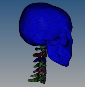
Mesh delineation is an essential process for building finite element models. HyperMesh was used to delineate the mesh in this study. Hexahedral and tetrahedral mesh are the two most dominant mesh forms in HyperMesh. The quality of the hexahedral mesh is relatively better, with fast calculation speed, high accuracy, and good convergence. However, tetrahedral meshes can conform well to complex geometric models and require simpler mesh generation. The anatomical structure of the human cervical spine is relatively complex, so this study adopted a tetrahedral structure to describe the geometric features of the cervical spine. The skull and C1-C7 vertebrae were modelled using solid elements, while the intervertebral discs were primarily simulated with shell elements. The anatomical contour features of the skull and vertebrae in the three-dimensional geometric model were delineated using HyperMesh software. Following element quality inspection and mesh refinement, a surface mesh was generated. Tetrahedral meshes were subsequently created via tremesh to establish the finite element model of the head-neck skeletal structure (Figure 1).
Figure 1: Finite element modelling of the head and neck bones.
The soft tissues in the head-neck region play critical roles in facilitating relative motion between adjacent skeletal structures, protecting the cervical spine, and preventing injuries caused by hyperflexion or hyperextension of the neck. The primary soft tissues include intervertebral discs, muscles, ligaments, and small joints. The main ligaments of the neck were the anterior longitudinal ligament, posterior longitudinal ligament, ligamentum flavum, interspinous ligament, and nuchal ligament. The major muscle groups included the cephalic longissimus, cervical longissimus, anterior rectus of the head, sternocleidomastoid, cervical broadissimus, trapezius, scapulars brevis, splenius, and deep muscle groups. Combined with the relevant knowledge of
Biomechanics Simulation and Damage Analysis of Head and Neck 193
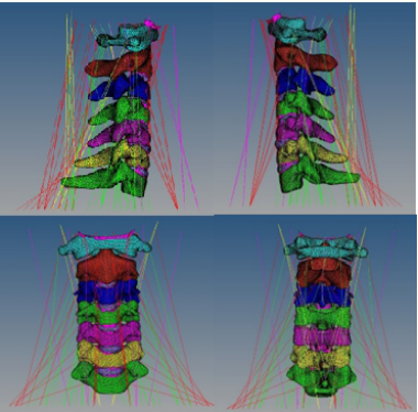
human anatomy and the mechanical properties of soft tissue, the specific position and starting and ending position of soft tissue were determined. The appropriate unit was selected to simulate the soft tissue, and on this basis, the grid was divided. Figure 2 showed the finite element model of the main muscles and ligaments of the neck.
Figure 2: Finite element model of major neck muscles and ligaments.
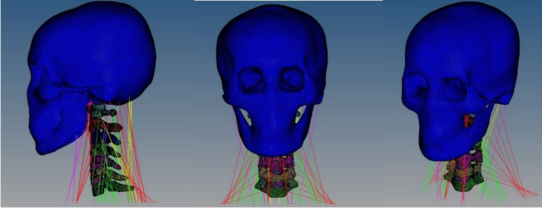
The head was connected to the neck through the atlanto-occipital joint and the ligaments at the atlanto-occipital joint, which completed the complete finite element model of the head and neck (Fig. 3). The model included 237,364 solid units, 4,696 spring units, and 366 beam units, totalling 242,426 units and 5,650 nodes. The contact type was set as face-to-face automatic contact with a coefficient of dynamic friction of 0.15 and a coefficient of static friction of 0.1 (Kumaresan et al., 1998).
Figure 3: Finite element model of human head and neck.
There are few experimental parameters for head and cervical materials in the existing literature, and most simulation studies used isotropic linear elastic materials. Based on the existing material parameters of the head and neck, this stduy scaled the lacking data accordingly by using
the parameters of similar structures according to the physiological and anatomical characteristics.
The main components of the skeleton are dense and cancellous bone. The mechanical properties of the two differ significantly, and the selection of material parameters is different. Elastoplastic materials were used to simulate the bone model, and the material parameters were selected from references (Camacho et al., 1999) (Table 1).
The intervertebral disc consists mainly of a central nucleus pulposus and a surrounding annulus fibrosus. The nucleus pulposus is an elastic, gelatinous substance. The annulus fibrosus consists of multiple layers of fibrocartilage arranged in concentric circles. The annulus fibrosus is under constant tension. Whether the intervertebral disc is under pressure or tension, the annulus fibrosus has different strength and stiffness values in different directions, and its material parameters were shown in Table 1.
Except for the ligaments around the joint capsule, the material parameters of the small joint parts could not be tested. This study used a linear elastic material to simulate the cartilage of the small joints, and its material parameters were shown in Table 1.
Ligaments have different functions, and the ratio between collagen fibers and elastic fibers in their collagenous tissues is also different, showing different mechanical properties. The neck’s collar ligament and ligamentum flavum comprise two-thirds of elastic fibers and mainly exhibit elastic properties. The other ligaments in the neck mostly comprise collagen fibers and exhibit plastic properties. The ligaments were modeled using linear elastic material properties (Delson et al., 1999), and the material parameters were shown in Table 1.
Table 1: Material parameters of bones and soft tissues.
Table available in the original PDF paper.
Items Young’s modulus
Poisson’s ratio Density g/cm3 /MPa Compact bone 1000 0.3 2.0 Cancellous bone 500 0.45 1.2 Intervertebral disc 200 0.35 1.5 Anterior
Muscle is mainly composed of muscle fibers. Its mechanical characteristics differ from other soft tissues, and the mechanical response is more complicated. In this study, only the passive force on the muscle was simulated.
Biomechanics Simulation and Damage Analysis of Head and Neck 195
The spring damping material was used to simulate the force, and its elastic damping coefficient was 0.017 (Kumaresan et al., 2001).
VALIDATION OF FINITE ELEMENT MODELS OF THE HEAD AND NECK The model needs to be validated before damage analysis can be performed. Currently, the validation methods commonly used for head and neck finite element models are the front and rear impact tests applied to study head and neck injuries in vehicle collisions (Ewing et al., 1968) and the head and neck cadaveric axial impact test (Mcelhaney et al., 1996). In traction life-saving, the overload direction is mainly axial, and the head and neck are mainly in flexion compression mode. Therefore, the axial impact test of the head and neck cadaver was used to verify the model.
This study compared the experimental results of head acceleration and collision force for 15
and 0
rigid plane collisions using Nightingale’s cadaver axial impact test with the simulation results. The simulation conditions of the finite element model of the head and neck were as follows: the model was in a 1 g conventional gravity field, the velocity of the head colliding with the rigid plane was 3.2 m/s, and the direction of the velocity was along the Z direction of the T1 thoracic vertebrae (in the vertical direction), while 16 kg of load was attached to simulate the effect of the torso on the head and neck during the collision.
Nightingale’s results for the 0
rigid plane collision test were as follows: after the head hit the 0
rigid plane, the impact force caused a tendency for the lower jaw of the sample’s head to extend forward, driving the cervical vertebrae to produce a large flexion deformation. The upper part of the cervical vertebrae, segments C2 to C3 and C3 to C4, produced extension deformations, while the lower part of the cervical vertebrae produced larger bending deformations.
Simulation calculations were performed by ANSYS software to load the model with the condition of 0
rigid plane collision, after which the simulation data results were obtained in LS-PrePost software. Comparing the motion trends of the cadaveric tests, it was found that the neck motion obtained by simulation was basically consistent with the description of the cadaveric experiments, which also produced the results of cervical spine extension at the upper segment and bending at the lower end, but the degree of deformation was smaller than that of the cadaveric tests.
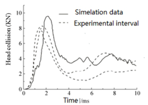
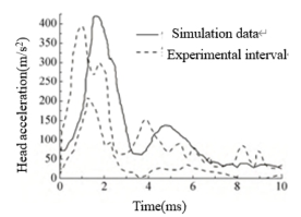
Experimental data on head impact forces for 0
rigid plane impacts (Nightingale et al., 1993) were shown as dashed lines in Fig. 4. The experimental intervals in the figure were the upper and lower values of the head collision force curves in multiple cadaver experiments. The solid line in Fig. 4 showed the head collision force data for the simulation using the head and neck finite element model in this study. The simulation time was the first 10 ms when the deformation was more concentrated. The peak moment point of the simulation curve was delayed by 1 ms compared with the experimental data. The waveforms of the simulation data coincided with the curve of the experimental interval.
Figure 4: Test data and simulation data of head impact force on 0◦rigid plane.
The results of the 15
axial impact rigid plane test on the neck of the cadaver head were compared with the simulation results. Under the 15
rigid plane impact condition, the neck of the model showed a trend of deformation similar to “S.” After impact, the lower jaw of the head still tended to extend forward, and the cervical spine had a large flexion deformation. The C2∼C4 segments of the upper cervical vertebrae and the C5∼C7 of the upper cervical vertebrae had larger deformation. The simulation results were basically consistent with the experimental description.
Under the condition of 15
rigid plane impact, the combined acceleration of the head is mainly verified. Similarly, the first 10 ms of deformation were simulated to compare with the literature (Nightingale et al., 1993). As shown in Fig. 5, the fluctuation of test curve was more, but the fluctuation of simulation curve was less. The peak moment of the combined acceleration of the simulation data was delayed by 1 ms compared with the experimental data, but the waveforms of the two were basically the same, and the peak of the combined acceleration was similar.
Figure 5: Test data and simulation data of human head combined acceleration on 15◦ rigid plane.
The comparison showed that the simulation results had a good similarity with the experimental results in terms of maximum combined head acceleration, maximum collision force and change trend. Due to the biological variability between the model and the real human body, there was a certain influence on the simulation results. In this model, the mechanical response of the head exhibited a certain degree of lag, but the cadaver experimental data and simulation results demonstrated consistent trends in their variations. The simulation model could genuinely reflect the actual
Biomechanics Simulation and Damage Analysis of Head and Neck 197
mechanical response of the head and neck, indicating that the established finite element model was reliable.
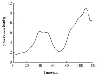
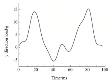
CALCULATION RESULTS AND ANALYSIS The traction lifesaving process is divided into two stages: ejection from the ejection tube and rocket traction. The sagittal (x-direction), coronal (z-direction), and vertical (y-direction) load data of the chest cavity were obtained from the mechanical sensors in the simulated dummy experiment. The y-direction data of the main loads in the ejection tube ejection and traction lifesaving stages were shown in Figs. 6 and Figs. 7. The effect of additional helmets on head and neck injuries in traction lifesaving was investigated by adding 1.02 kg of helmet mass to the head mass. On this basis, the loads were loaded at all unit nodes at the bottom, and the bottom muscles and C7 were rotationally constrained in the x, y, and z directions. The whole model was in a regular gravity field (1 g). The simulation time for the ejection phase of the ejection tube was about 120 ms, and the simulation time for the tractor rocket phase was about 100 ms.
Figure 6: Load of y direction of the ejection phase.Figure 7: Load of y direction of towed rocket stage.
The model was loaded in x, y, and z directions during one-shoulder diagonal pulling. The model was subjected to a z-direction load during
double-shoulder traction. After calculation by ANSYS software, LS-Prepost software exported the deformation trend, combined acceleration of the head, and relative acceleration and relative velocity of the cervical atlantoaxial vertebrae and the bulge vertebrae in the horizontal direction of the head and neck model during the single-shoulder diagonal pulling traction and double-shoulder traction.
Due to the deformation of the human head and neck during the traction lifesaving process, whether the tolerance limit of the human body was exceeded need to be judged according to the relevant criteria. The HIC criterion (Equation (1)), which is widely used for head injury judgment (Lissner et al., 1960), and the NIC criterion (Equation (2)) t (Aldman et al., 1997), which is widely used for neck injury judgment, were used. The combined acceleration of the head and the relative velocity and acceleration of the horizontal direction of the atlas and spine of the neck were derived. The HIC and NIC values were calculated during traction lifesaving as the basis for head-neck injury evaluation.
2·5
Z t2
(1)
R (t) t
(t2 −t1)
1 t2 −t1 t1 max
Where: R(t) is the linear acceleration of the centre of inertia of the head (g); t1 is the impact start time (s); t2 is the impact end time (s); t is the time variable (s).
NIC = a × 0.2 + v2(2) (2) Where: a is the relative acceleration in the horizontal direction between the vertebrae of the upper and lower cervical vertebrae in m/s2; v is the relative velocity in the horizontal direction between the vertebrae of the upper and lower cervical vertebrae in m/s; and 0.2 is a constant in m. The relative acceleration between the vertebrae of the upper and lower cervical vertebrae in m/s was calculated as follows.
The HIC criterion specifies that HIC = 1000 is the threshold of linear acceleration tolerance of the head (Bostrom et al., 2000). The calculation results showed that the maximum value of the model of the head in the ejection stage of the ejection tube of the one-shoulder diagonal pull traction process was 317.8, and the maximum value in the traction rocket stage was 647, which was much less than 1,000, so the probability of head injury was low under this condition.
The maximum value of the ejector tube ejection phase in one-shoulder diagonal traction was 7.74 m2 /s2, which was less than the tolerance value of 15 m2 /s2 for NIC, while in the traction rocket phase, the maximum value was 26.06 m2 /s2, which was more than the critical value of 15 for NIC injury. Therefore, the probability of neck injury in the ejection phase of the ejection tube during single-shoulder diagonal traction life-saving was low, and the probability of neck injury in the traction rocket phase was high.
The maximum value of NIC in the ejection stage of the ejection tube during double shoulder traction was 7.9 m2 /s2, which was less than the tolerance
Biomechanics Simulation and Damage Analysis of Head and Neck 199 value of NIC 15 m2 /s2. In the rocket traction phase, the maximum NIC value was 36.1 m2 /s2, which exceeded the NIC injury threshold of 15; therefore, the probability of neck injury in the ejection phase of the ejector cartridge in the two-shoulder life-saving traction process was low, and the probability of neck injury in the rocket traction phase was high.
CONCLUSION
In this paper, a finite element model of the human head and neck was established based on the pilot’s body size standard, encompassing the skull, vertebrae, intervertebral discs, as well as muscles, ligaments, and other soft tissues. The collision forces and combined head acceleration values of 0
and 15
rigid plane axial impact collisions were simulated and calculated. Through comparative analysis with the data measured in cadaver experiments, the effectiveness of the model was verified.
Head and neck movements were simulated during one-shoulder oblique and two-shoulder traction. The head and neck injuries were determined according to the HIC and NIC guidelines, and it was found that the head did not have an exceedingly high injury tolerance limit and had a low probability of producing an injury during the traction rocket phase of the one-shoulder diagonal and two-shoulder traction processes, whereas the neck exceeded the body’s tolerance limit and had a high probability of producing an injury.
REFERENCES
Aldman, B., Bostrom, O., Svensson, MY. et al. (1997). A New Neck Injury Criterion Candidate-Based on Injury Findings in the Cervical Spinal Ganglia After Experimental Neck Extension Trauma, International Conference on the Biomechanics of Impacts. Bostrom, O., Bohmarin, K., Haland, Y. et al. (2000). New ASI1 Long-Term Neck
Injury Criteria Candidates Based on Rear Frontal Crash Analysis, International Research Council on the Biomechanics of Injury. Camacho, DL., Nightingale, RW., Myers, BS. (1999). Surface Friction in Near- Vertex Head and Neck Impact Increases Risk of Injury, Journal of Biomechnical Engineering, Volume 32, No. 3. Dai, Jiming., Peng, Yong., Yang, Jikuang. (2013). Influence of Neck Dynamic
Response on Head Injuries in Passenger Car to Pedestrian Collisions, Proceedings of the 10th Int. Forum of Automotive Traffic Safety (INFATS). Delson, N., Panjabi, MM., Wang, JL. (1999). Neck Injury Criterion Based on Intervertebral Motions and Its Evaluation Using an Instrumented Neck Dummy, International Ircobi Conference on the Biomechanics of Impact. Ewing, C., Patrick, L., Thomas, D. et al. (1968). Dynamic Response of the Head and
Neck of the Living Human to -Gx Impact Acceleration, 12th Stapp Car Crash Conference. Jiang, Wen. (2012). The Impact Analysis of the Human Head and Neck Injuries in High-Speed, Tianjin: Tianjin University of Science and Technology. Kumaresan, S., Pintar, FA., Yoganandan, N. (1998). Finite Element Modelling
Approaches of Human Cervical Spine Facet Joint Capsule, Volume 31, No. 4.
Kumaresan, S., Pintar, FA., Yoganandan, N. (2001). Biomechanics of the Cervical Spine Part 2. Cervical Spine Tissue Responses and Biomechanical Modelling, Clinical Biomechanics, Volume 16 No. 1. Li, Na. (2010). Study of Finite Element Model of Human Head and Neck Injuries in
Collision, Changsha: Central South University. Lissner, HR. (1960). Experimental Studies on the Relation Between Acceleration and Intracranial Pressure Changes in Man, Surgery Gynecology & Obstet Volume 29 No. 3. Lu, Yan., Liu, Songyang., Wang, Yawei. et al. (2012). Dynamic Responses of Head-
Neck Complex in Pilots During Arrested Deck Landing, Journal of Medical Biomechanics Volume 27, No. 6. Mcelhaney, JH., Nightingale, RW., Richardson, WJ. et al. (1996). Dynamic Responses of the Head and Cervical Spine to Axial Impact Loading, Journal of Biomechanics Volume 29, No. 3. Wan, Xinming., Yang, Jikuang., Xu, Wei. (2005). Development and Validation of a
Head-Neck Finite Element Model for the Study of Neck Dynamic Responses in Car Impacts, Journal of Human University (Natural Sciences), Volume 32, No. 2.
LISTED IN THE AHFE DIGITAL BOOKSTORE CATALOGUE
Explore the complete digital volume
Accessibility, Assistive Technology and Digital Environments
Read this individual research paper free through the original publisher, or explore the full digital proceedings book.
ISBN 978-1-964867-38-0
Explore this ISBN in the AHFE Bookstore ↗Listed in the July 2026 bookstore catalogue; search by ISBN to confirm current availability · Digital book purchase optional