Emilia Visileanu, Adrian Salistean, Alexandra Gabriela Ene, Radu Herzog, Razvan Scarlat (2026). Automated Hemostasis in Limb Trauma: FEM Insights for Tourniquet Optimisation. In: Healthcare and Medical Devices. AHFE Open Access, vol. 211, pp. 68–78. https://doi.org/10.54941/ahfe1007469
Haemorrhage is the leading cause of preventable death in military operations, often resulting from explosions, gunshots, stabbings, or cuts. Limbs are particularly vulnerable, accounting for nearly 55% of combat-related injuries, and rapid blood loss can lead to over half of deaths within minutes and almost one-third within hours. These statistics highlight the urgent need for rapid and reliable haemorrhage control, particularly in situations where immediate human intervention may be delayed or impossible.To address this critical problem, an automated primary hemostasis system was developed to arrest bleeding without human assistance. The design of its signal-triggering mechanism was informed by finite element method (FEM) simulations, which provided a quantitative understanding of tissue mechanics under tourniquet application. Human soft tissues exhibit complex behaviour due to their multilayered structure, heterogeneity, anisotropy, and viscoelasticity, necessitating nonlinear constitutive models. In this work, skin, subcutaneous adipose tissue, and muscle were modelled as nearly incompressible, isotropic hyperelastic materials using a Neo-Hookean formulation, whereas bones were considered rigid. The Neo-Hookean model captures tissue response through two key parameters: the shear modulus, which governs deformation under shear, and the bulk modulus, which defines resistance to volumetric compression.A detailed three-dimensional model of the upper limb was reconstructed from biomedical imaging data, including skin, adipose tissue, muscle, and humeral bone. The discretised model comprised over 850,000 tetrahedral elements, with material properties assigned according to tissue type and scaled to anatomical geometry. Boundary conditions permitted free displacement of soft tissues, while bone nodes were constrained axially. Tourniquet application was simulated by imposing prescribed displacement fields derived from three-dimensional indentation maps. To ensure numerical stability in the presence of nonlinear tissue behaviour, compression was applied incrementally using a conservative predictor strategy.Simulation results revealed striking patterns of tissue deformation. Maximum displacement occurred at the tourniquet centre, predominantly in the radial direction, while axial displacement dominated regions outside the compressed zone. Muscle surface strain increased progressively with compression intensity and exhibited a diffuse spatial distribution, whereas stress concentrations were localised at tissue interfaces. These mechanical patterns were interpreted in the context of physiological blood flow, both at rest and during intense exertion. Elevated arterial pressure and increased flow rates accelerate haemorrhage, shortening the window for effective intervention and emphasising the importance of timely hemostatic control.Integrating FEM-based tissue mechanics with hemodynamic considerations provides critical insights into the efficiency of haemorrhage control strategies. This approach not only informs the design and optimisation of tourniquets but also guides the development of automated hemostasis systems capable of rapid deployment in high-risk scenarios. By linking quantitative tissue deformation with clinical outcomes, the study offers a powerful framework for improving survival rates in military and civilian trauma situations, highlighting how biomechanical modelling can directly influence life-saving interventions.
Trauma is a leading cause of death and disability worldwide, with uncontrolled haemorrhage representing a major and often preventable cause of mortality, particularly in youngand active populations (Sauaia A., Moore, F.A., Moore, E.E. et al., 1995; Eastridge, B.J, Mabry, R.L., Seguin, P. et al., 2012).
Extremity injuries are especially critical, as rapid blood loss can lead to hypovolemic shock within minutes, creating a narrow window for life-saving intervention (Kotwal, R.S., Montgomery, H.R., Kotwal, B.M. et al., 2011;
Automated Haemostasis in Limb Trauma: FEM Insights for Tourniquet Optimisation 69 Owens, B.D., Kragh, J.F., Wenke, J.C et al., 2008; Kauvar, D.S, Wade, C.E, 2005). In both military and civilian settings, tourniquets have re-emerged as a vital intervention for severe limb bleeding, demonstrating improved survival when applied correctly (Kragh, J.F, Walters, T.J., Baer, D.G. et al., 2009; Lakstein, D., Blumenfeld, A., Sokolov, T. et al., 2003). However, timely and skilled human application is not always possible in battlefield, mass casualty, or remote scenarios, motivating the development of automated haemorrhage control systems capable of detecting bleeding and applying therapeutic compression without direct human involvement (Rhee, P., Guyton, A.C., Hall, J.E., 2021). Designing such systems requires a detailed understanding of the biomechanical response of soft tissues to circumferential compression. The human upper limb consists of multiple layers—skin, fat, muscle, fascia, vasculature, and bone—each with distinct mechanical properties (Fung, Y.C., 1993; Humphrey, J.D., 2003). Soft tissues exhibit nonlinear, anisotropic, viscoelastic, and nearly incompressible behaviour, complicating the prediction of deformation under external loads. Hyperelastic models, particularly Neo- Hookean formulations, provide a computationally efficient approach to capture tissue mechanics under large deformation conditions (Holzapfel, G.A., 2000). The finite element method (FEM) enables precise analysis of stress, strain, and displacement distributions in anatomically realistic models (Taylor, M., Prendergast, P.J., 2015); Viceconti, M., Bellingeri, L., Cristofolini, L., Toni, A.,1998). Advances in imaging techniques such as CT and MRI facilitate subject-specific three- dimensional reconstructions, allowing high-resolution simulations that capture tissue-device interactions and predict mechanical outcomes of tourniquet application (Viceconti, M., Henney, A., Morley-Fletcher, E., 2016). Effective haemorrhage control also depends on haemodynamic factors—arterial pressure, vascular compliance, and blood flow dynamics which influence vascular occlusion and bleeding rates (Guyton, A.C., Hall, J.E., 2021). Integrating FEM-based biomechanics with physiological considerations provides a comprehensive framework for optimising haemorrhage control interventions. This study employs a high- resolution FEM of the upper limb, incorporating hyperelastic soft tissues and rigid skeletal constraints, to simulate tourniquet- induced compression. By analysing tissue deformation, stress, and displacement patterns in relation to haemodynamic conditions, the research aims to inform the design of automated primary haemostasis systems, advancing rapid, reliable bleeding control in both military and civilian trauma care (Viceconti, M., Pappalardo, F., Rodriguez, B. et al., 2021).
DEFORMATION AND ITS ROLE IN OPTIMIZING THE TOURNIQUET FOR AUTOMATIC HEMOSTASIS In the context of automated hemostasis for limb trauma, the analysis of tissue deformation represents an essential element for defining the optimal parameters of the circumferential compression exerted by a tourniquet.
Deformation is a normalised, dimensionless quantity that describes the internal configurational changes of a deformable body and the relative displacements between its particles. In the case of uniaxial loading, deformation is defined as the ratio between the change in length and the
initial length, expressed in fractional form. In linear elastic materials, the stress–strain the relationship is proportional up to a certain limit, where the slope of the linear region represents the modulus of elasticity.
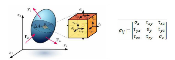
However, soft biological tissues exhibit a non-linear, viscoelastic, and nearly incompressible behaviour, which requires the use of finite strain theories to realistically describe mechanical behaviour under high compression, such as the application of a pneumatic tourniquet. In a general loading regime, the Cauchy stress tensor describes the internal stress state for small deformations (see Figure 1).
Figure 1: Cauchy stress tenso.
However, for large deformations and nonlinear behavior - characteristic of the circumferential compression exerted by a tourniquet - it is necessary to use finite strain theory and Piola–Kirchhoff tensors. The relationship between the Cauchy stress tensor and the second-order Piola–Kirchhoff tensor allows for the correct description of force transfer under conditions of significant deformation: S = J F–¹ σ F–T (1)
where S is the second Piola–Kirchhoff tensor, F is the strain gradient, and J = det(F) represents the volumetric strain ratio.
In the context of tourniquet optimization, the analysis of the eigenvalues of the stress and strain tensors (principal stresses and strains) allows the identification of areas at high risk of tissue damage or excessive ischemia. Thus, numerical modelling becomes an essential tool for balancing haemostatic efficiency with tissue safety.
MECHANICAL MODELS OF SOFT TISSUES IN TOURNIQUET COMPRESSION SIMULATION Human soft tissues are multilayered, inhomogeneous, and anisotropic. Their mechanical properties depend on age, anatomical location, and physiological state. Viscoelastic behaviour involves phenomena such as creep, stress relaxation, and hysteresis under cyclic loading.
Applying a tourniquet induces large deformations, and the stress-strain relationship is strongly nonlinear. For this reason, hyperplastic modelling provides a suitable approach. Hyperplastic materials are described by a strain energy density function W, from which the constitutive relationship is derived.
The Neo-Hookean model, used in this research, defines the strain energy as follows:
Automated Haemostasis in Limb Trauma: FEM Insights for Tourniquet Optimisation 71 W = (μ/2) (Ī1 − 3) + (κ/2) (J − 1)² (2)
where: μ is the shear modulus, κ is the compressibility modulus, Ī1= Tr (F–T.F–) is the first invariant of the modified Cauchy–Green tensor, J = det(F) is the elastic volume ratio, F is the deformation gradient tensor, F– = J−1⁄3. F is the isochoric component of the deformation gradient tensor, and Tr is the trace of a matrix. This model allows realistic simulation of circumferential compression induced by tourniquets and evaluation of stress distribution in skin, adipose tissue, and muscle. The correct choice of parameters μ and κ is essential for determining the threshold of vascular occlusion without exceeding tissue safety limits.
COMPUTATIONAL MODELING (FEM) FOR TOURNIQUET COMPRESSION OPTIMIZATION The finite element method (FEM) represents the primary numerical framework used to evaluate device-tissue interaction. The continuous domain of the upper limb was discretized into tetrahedral elements, enabling the computation of displacement, stress, and strain fields.
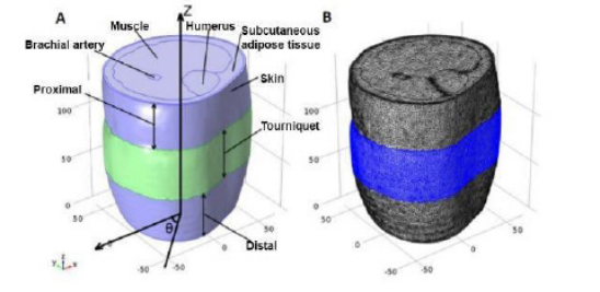
Volumetric Reconstruction The model geometry included 4 anatomical structures: skin, subcutaneous adipose tissue, muscle, and bone (humerus). 3D segmentation and visualization of soft and hard tissue image data were derived from biomedical 3D images of the upper limb (see Figure 2A).
Figure 2: Volumetric reconstruction (A); 3D Discretized Model (Mesh) (B).
Mesh Generation The model included: 853,711 tetrahedral elements, 175,753 triangular elements, and 624,836 degrees of freedom (Fig. 2B). The total model volume was 1,685,420 mm³, divided into skin: 106,600 mm³; subcutaneous adipose: 438,200 mm³; muscle: 1,033,000 mm³; humerus: 97,370 mm³. Additionally, 2 surfaces were defined around the bony structures representing hard tissue layers with areas of 5,167 mm² and 14,660 mm² for the bone surfaces, respectively.
This high resolution enabled detailed evaluation of deformation distribution relative to the tourniquet’s axial position.
Material Parameters The 3D placed model was exported to the finite element solver (Ansys Fluent) to define material properties and boundary conditions. The mechanical properties of skin, subcutaneous adipose, and muscle were considered nonlinear, isotropic, and hyperelastic, using a nearly incompressible version of the Neo-Hookean strain energy density function. The bulk modulus (κ) and shear modulus (μ) of various soft tissues were correlated with the 3D model size. The material constants used for simulating skin, subcutaneous adipose and muscle tissue are shown in Table 1.
Muscle 7.44 116 Boundary Conditions: all nodes of the 3 soft tissue layers were left free to displace in space in all directions (Study I, II). The boundary condition for the bony structure nodes was defined as a fixed constraint, meaning they had no displacement in space during the simulation. These nodes were constrained only in the axial direction of the model, allowing relative or absolute displacement in the transverse plane (xy plane), but their displacement in the axial direction (z-axis) was zero. The extracted 3D indentation maps were converted from the cylindrical coordinate system to the Cartesian system and applied to the external surface of the model as prescribed displacements, simulating external boundary conditions at tourniquet compression intensities.
Simulation: Indentation intensities increased incrementally in steps of 0.5 mm during simulation progression to prevent convergence issues, which are very common in running hyperplastic models. Also, due to the high nonlinearity of this model, a conservative and robust approach with a constant predictor was used during the solution. This technique relies on using the final condition of one simulation stage as the initial condition for the next stage. Finally, when the prescribed displacement boundary conditions reached real magnitudes, the running process was stopped, and the solution was finalized. Indentation fields, stress and strain distributions of each soft tissue layer were extracted from the solved model. Additionally, the stress and strain model on the external surface of the bony structures and on the muscle surface was obtained.
This approach enabled progressive simulation of tourniquet pressure increase and identification of critical deformation thresholds.
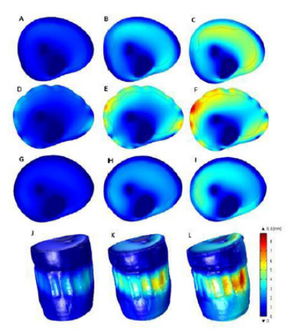
FEM RESULTS AND IMPLICATIONS FOR AUTOMATIC HEMOSTASIS Based on FEM simulations, the deformation model during increasing tourniquet compression intensity is presented in Figure 3 for medio- transversal planes located distal to the tourniquet (A, B, C), proximal to the tourniquet (G, H, I) and at the tourniquet position (D, E, F).
The 3D deformation field of the entire model is shown in the last row. The deformation peaks at the tourniquet location, where the tissues are directly subjected to compression.
FEM simulations show that deformation intensity was dependent on axial position. As expected, tissues within the tourniquet region were more stimulated compared to tissues outside the tourniquet region. The 3-dimensional analysis illustrated that the maximum deformation occurred approximately at the level located at the center of the tourniquet (see Figure 3 J, K, L).
Figure 3: Whole tissue deformation during tourniquet compression in transverse planes.
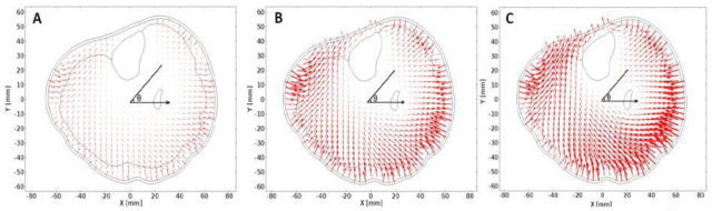
Nodal Displacement Field The 2-dimensional nodal displacement field for the transverse plane located at the center of the tourniquet position at 3 compression intensities, and the 3- dimensional displacement field for the loaded tourniquet state, extracted from the finite element simulation, are shown in Figure 4. Each vector indicated the magnitude and direction of the displacement of each node forming the finite element model. The indentation vectors showed that tissues outside the tourniquet area were more subjected to axial displacement, whereas tissues under the tourniquet were subjected to radial displacement.
Figure 4: 2-dimensional displacement field in the medio-transverse plane of the tourniquet region in the non-actuated state (A), normally loaded state (B), and maximally loaded state (C).
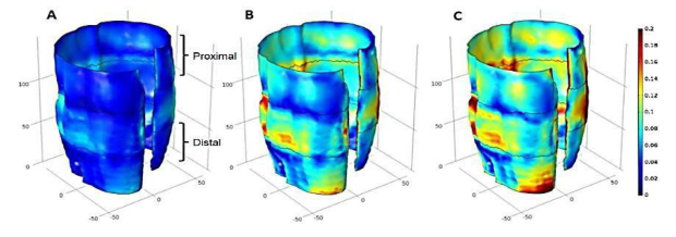
Surface Strain Distribution Strain showed an increasing trend on the muscle surfaces (see Figure 5 A, B, C) as tourniquet compression intensity increased. The strain on the muscle surface was not concentrated in a specific region and was more widely distributed compared to the stress on this surface.
Figure 5: Stress distribution on the muscle surface (A, B, C) at different tourniquet compression intensities.
Simulations demonstrated: maximum deformation at the center of the tourniquet position, an axially dependent distribution of mechanical loads, radial displacements under the tourniquet and axial displacements in adjacent regions, and a progressive increase in stresses with increasing compression intensity. These results provide essential information for defining the minimum pressure required for arterial occlusion, preventing overcompression and tissue necrosis, and designing an adaptive pressure control algorithm
AUTONOMOUS PRIMARY HEMOSTASIS SYSTEM – FEM RESULTS INTEGRATION The developed system consists of an intelligent undergarment equipped with the following components: a conductive textile structure for injury detection, a control unit, a pneumatic pump, and proximally placed pneumatic tourniquets. Automatic activation is triggered by interruption of the electrical circuit in the conductive textile structure in the event of a wound (gunshot,
Automated Haemostasis in Limb Trauma: FEM Insights for Tourniquet Optimisation 75 stabbing, cutting). The control unit activates the pump, which inflates the tourniquet until the preset pressure is reached. Circumferential compression must exceed systolic arterial pressure to stop distal blood flow. Loss of more than 40% of blood volume can cause irreversible hypovolemic shock, which justifies the need for immediate intervention.
Correlation With FEM Results The main factors influencing the extension of a textile structure are: fibre composition (cotton, wool, polyester, elastane, etc.), knit type (jersey, rib, double- knit, etc.), stitch density, and yarn length density. Extension is essential for the comfort of textile structures, as it allows body fit and ensures the wearer’s freedom of movement. Extension is calculated using the formula:
F kgf Ex (3)
( ) L(cm) = ∆ where: F = applied force; ΔL=Lf-Lo(cm); Lf = final length (after force application), cm; Lo = initial length, cm.
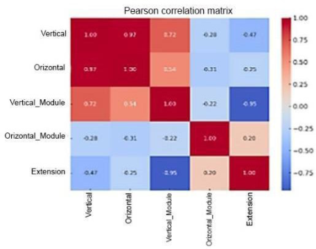
The Pearson correlation coefficients between elastic modulus, elongation, and vertical and horizontal extension (knits) show: a strong positive correlation (r ≈ 0.97) between vertical and horizontal elongation, a strong negative correlation between vertical modulus and extension (r ≈ −0.95) and no significant correlation of the horizontal modulus with the other variables (low values).
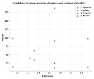
Figure 6 shows the heatmap-style correlation plot where red colors indicate strong positive correlations (values close to +1), blue colors indicate strong negative correlations (values close to −1), and lighter or nearly white colors indicate weak correlations or values close to 0. For woven structures all correlations are negative, so when elongation increases, extension decreases. The strongest relationship is between horizontal extension and horizontal elongation(r = −0.94), (see Figure 7).
In Figure 8, a male mannequin with realistic proportions is shown in a T-pose (the standard for 3D models), high-poly (arms, legs, head, face, etc.). The mannequin is equipped with the primary haemostasis system consisting of a conductive textile structure, a tourniquet applied on the arm connected via tubes and wires to the control unit and pump, a protection system, and a control button, all visible.
Figure 8: Male mannequin equipped with a primary haemostasis system.
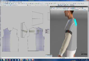
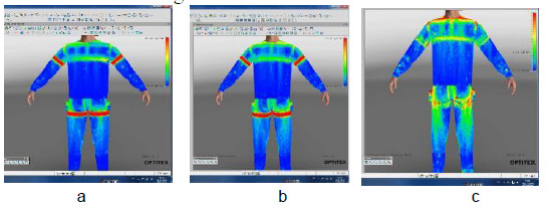
Using the specialised OPTITEX software, the tension map of the ensemble, including the activated primary hemostasis system (under pressure) driven by the pump and control unit, was determined. The material characteristics were entered into the software’s property table. The areas of material deformation under applied force were visualised. 4 zones were distinguished: a red zone with pronounced deformation, appearing in the product’s support areas on the body (shoulders of the blouse, t h e waistband of the trousers). The red colour is also observed in the tourniquet area because it is thicker than the base material and closer to the body, especially for woven structures, which are stiffer. The blue zone corresponds to maximum comfort, where the material is away from the body, and no deformation occurs. Green and yellow zones indicate that the material approaches the body but does not cause discomfort.
The tourniquet was subjected to a pressure of 200 mmHg on the arm (3.8 psi) and 280 mmHg (5.4 psi) on the leg and was analysed numerically to determine: the effective pressure transmitted to the tissues (gf/cm²), the surface stress distribution, and regions with increased biomechanical risk. In
Automated Haemostasis in Limb Trauma: FEM Insights for Tourniquet Optimisation 77 Figures 9a, 9 b, and 9c, the stress maps are shown for the static position of the tourniquet and for the pressurised positions on the arm and leg.
Figure 9: Tourniquet stresses: a. static position, b. activation on the upper limb, c. activation on the lower limb.
In the static position, the tourniquet exerts an average pressure on the body of 3.3 gf/cm² (green range of the tension scale in the tourniquet area), within comfortable wear limits. At a tourniquet pressure of 220 mmHg (4.25 psi) on the upper limb, this results in a body pressure of 17.16 gf/cm² (as seen in the red range of the tension scale in the tourniquet area). At a tourniquet pressure of 280 mmHg (5.41 psi) on the leg, the resulting body pressure is 20.28 gf/cm² (as shown on the tension scale), with maximum values in red in the tourniquet area. The results showed that: static pressure (~3.3 gf/cm²) falls within comfort limits, therapeutic pressures (17– 20 gf/cm²) generate red zones of intense loading in the tourniquet region, and stress distribution depends on the rigidity of the textile structure (woven vs. knitted).
CONCLUSION
The study develops a detailed biomechanical model of the human upper limb to analyse the effects of circumferential compression, such as tourniquet application, on tissues and blood vessels. The results provide insights into tissue deformation, stress, and displacement, supporting the design of automated haemostasis systems and contributing to the development of intelligent rapid- bleeding control technologies.
ACKNOWLEDGMENT
This research was funded by the Romanian National Authority for Research, under the National Research Program 5.7- Partnership for Innovation, Subprogram 5.7.1- Partnerships for Competitiveness, Experimental Demonstrative Project PN-IV-P7- 7.1-PED-2024-0353, contract no.56PED/2025.
REFERENCES
Eastridge, B.J., Mabry, R.L., Seguin, P. et al. (2012). Death on the battlefield (2001– 2011): implications for the future of combat casualty care. Journal of Trauma and Acute Care Surgery, 73(6): S pp.431–S437. Fung, Y.C. (1993). Biomechanics: mechanical properties of living tissues, Springer. Guyton, A.C., Hall, J.E. (2021). Textbook of medical physiology, Elsevier. Holzapfel, G.A. (2000). Nonlinear solid mechanics: a continuum approach for
engineering, Wiley. Humphrey, J.D. (2003). Continuum biomechanics of soft biological tissues, Proceedings of the Royal Society A, pp.459:3–46. Kauvar, D.S., Wade, C.E. (2005). The epidemiology and modern management of
traumatic haemorrhage, Critical Care, 9(Suppl 5), pp. S1–S9. Kotwal, R.S., Montgomery, H.R., Kotwal, B.M. et al. (2011). Eliminating preventable death on the battlefield. Archives of Surgery, 146(12), pp. 1350–1358. Kragh, J.F., Walters, T.J., Baer, D.G. et al. (2009). Survival with emergency tourniquet
use to stop bleeding in major limb trauma, Annals of Surgery, 249(1), pp.1–7. Lakstein, D., Blumenfeld, A., Sokolov, T. et al. (2003). Tourniquets for haemorrhage control on the battlefield, Journal of Trauma, 54(5), pp. S221–S225. Owens, B.D., Kragh, J.F., Wenke, J.C. et al. (2008). Combat wounds in Operation
Iraqi Freedom and Operation Enduring Freedom, Journal of Trauma, 64(2), pp. 295–299. Rhee, P., Brown, C., Martin, M. et al. (2008). QuikClot use in trauma for haemorrhage control, Journal of Trauma, 64(4), pp. 1093–1099. Sauaia A., Moore, F.A., Moore, E.E. et al. (1995). Epidemiology of trauma deaths: a
reassessment. Journalof Trauma, 38(2), pp. 185–193. Taylor, M., Prendergast, P.J. (2015). Four decades of finite element analysis of orthopaedic devices, Journalof Biomechanics, 48(5), pp. 767–778. Viceconti, M., Bellingeri, L., Cristofolini, L., Toni, A. (1998). A comparative study
on different methods of automatic mesh generation of human femurs, Medical Engineering & Physics, 20(1), pp. 1–10. Viceconti, M., Henney, A., Morley-Fletcher, E. (2016). In silico clinical trials: how computer simulation will transform the biomedical industry, International Journal of Clinical Trials, 3(2), pp. 37–46. Viceconti, M., Pappalardo, F., Rodriguez, B. et al. (2021). In silico trials: verification,
validation and uncertainty quantification of predictive models used in the regulatory evaluation of biomedical products, Methods, 185, pp. 120–127.
LISTED IN THE AHFE DIGITAL BOOKSTORE CATALOGUE
Explore the complete digital volume
Healthcare and Medical Devices
Read this individual research paper free through the original publisher, or explore the full digital proceedings book.
ISBN 978-1-964867-87-8
Explore this ISBN in the AHFE Bookstore ↗Listed in the July 2026 bookstore catalogue; search by ISBN to confirm current availability · Digital book purchase optional